How to Measure Neutral Current in Three-Phase Four-Wire Systems
Neutral current measurement in a three-phase four-wire system requires a suitable current sensor around the neutral conductor alone, a documented measurement location, and readings taken during representative loading. Measure the three phase currents as well when diagnosing imbalance or harmonics. A calculated neutral value from phase channels is useful only when the instrument captures synchronized waveforms and applies the correct calculation. Adding three displayed RMS phase readings does not produce neutral current. This guide explains how to plan the measurement, distinguish different return-current paths, and produce a useful engineering record before considering changes to loads, conductors, or compensation equipment.
Define the measurement boundary first
Start with the question the measurement must answer. You may need to check a particular feeder, investigate heating, establish a loading trend, or determine whether triplen harmonics contribute to a neutral-current problem. These questions require different recording periods and sometimes different sensors. A single reading is evidence about one operating condition, not a full description of the installation.
Identify the supply arrangement from current drawings and site inspection. Confirm that the feeder actually has a neutral and that it is distinct from the protective conductor at the intended measurement point. A combined protective-and-neutral conductor requires particular care and an installation-specific procedure. Do not assume that every fourth conductor is an ordinary neutral or that its current has the same interpretation throughout the distribution system.
Record the feeder identifier, upstream transformer or source, connected loads, measurement point, and any parallel neutral paths. If multiple neutral conductors serve the same circuit, a measurement around just one represents that conductor’s share. The engineer must establish the intended boundary before interpreting the result. Photographs and a marked drawing help later reviewers understand what was measured.
Select a suitable current sensor
A clamp or flexible current probe must have the electrical category, voltage rating, current range, conductor capacity, and frequency response required for the location and task. These are independent properties. A sensor with a large current range can still have inadequate harmonic bandwidth or an unsuitable installation rating. Check the sensor and recorder combination, not just the probe label.
For an initial load survey, true-RMS measurement matters because nonlinear loads can produce distorted waveforms. For harmonic diagnosis, request specified amplitude and phase performance over the frequency range under investigation. A general-purpose clamp may give a useful total-current reading without producing a defensible harmonic spectrum. Specify the recording and analysis functions separately.
Traditional current transformers, voltage-output sensors, and flexible coils have different connection requirements. Use the sensor type supported by the instrument and the manufacturer’s connection procedure. Never connect a conventional current-output CT to an input intended for a voltage-output probe. Never open a conventional CT secondary while primary current flows. Any installation requiring access to conductors belongs to qualified personnel using the site’s approved electrical work procedure.
Distinguish ordinary panel indication from diagnostic recording
The BY194 series multifunctional power instrument illustrates the panel-meter context in which phase-current data may already be available. Its product photograph does not prove a dedicated neutral-current input, harmonic recording, or the measurement class of a specialist analyzer. Confirm the exact model’s manual, input configuration, and available data before including it in the measurement plan.
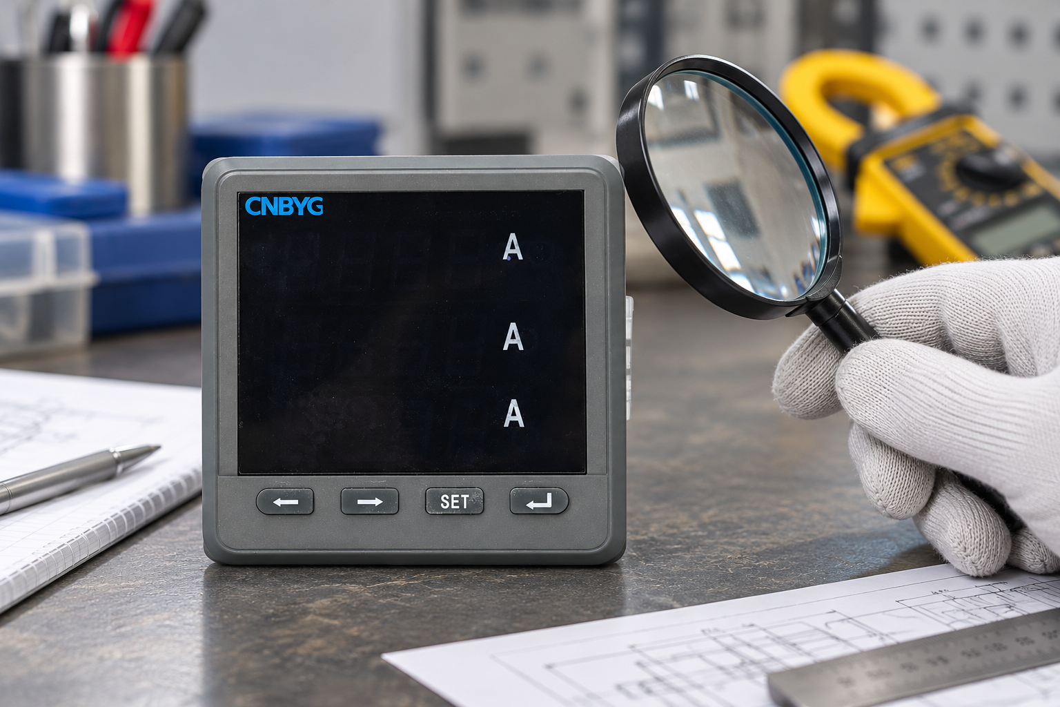
Existing panel readings can help identify operating periods and load changes. They cannot replace a missing neutral channel or establish the frequency response of a portable probe. If the needed information is unavailable, specify an appropriate temporary measurement instrument rather than assigning undocumented capabilities to the installed meter.
For broader measurement planning, use the power quality survey guide and the power quality meter placement guide. Those discussions help define the survey boundary and measurement locations; this article concentrates on the neutral-current measurement itself.
Prepare a safe and repeatable measurement
Prepare the work procedure before opening equipment or positioning probes. Determine whether the task requires isolation, approved live-work measures, or installation of sensors during a planned shutdown. An insulated clamp does not make an otherwise unsafe approach acceptable. Follow the site’s access rules and the instrument manufacturer’s instructions.
Where a clamp can be placed safely, enclose the neutral conductor alone. Enclosing phase and neutral together measures their combined magnetic effect and changes the question being answered. Ensure the jaw closes fully, the conductor fits within the specified opening, and the probe is placed as instructed. Nearby conductors and mechanical interference can affect some sensors.
Record sensor identification, range, orientation, and zero adjustment where applicable. Select a range that covers expected peaks without sacrificing necessary resolution. A displayed value near zero may indicate a lightly loaded neutral, insufficient resolution, a setup error, or cancellation caused by enclosing the wrong conductors. Check the setup before concluding that the installation has no neutral-current issue.
For a recorder, enter the sensor scaling and channel labels carefully. Verify the indicated current against a known operating condition or a suitable independent instrument when practical. Check timestamps and synchronization before correlating neutral current with load operation. Document any channels that were unavailable instead of silently treating missing data as zero.
Use a measurement checklist
The following table gives qualitative checks, not universal operating limits. Acceptance criteria depend on the installation design, instrument specifications, applicable requirements, and the engineering question.
| Check | What to document | Why it changes interpretation |
|---|---|---|
| System arrangement | Three-phase four-wire boundary and neutral identity | Prevents confusing neutral, protective, or combined conductors |
| Sensor enclosure | Exactly which conductor or conductor group is enclosed | Determines whether the value represents neutral current or residual current |
| Range and scaling | Probe range, recorder setting, and conversion factor | Incorrect scaling can make all recorded amplitudes wrong |
| Frequency response | Verified probe and recorder capabilities | A total RMS result does not establish harmonic accuracy |
| Operating state | Loads running, source configuration, and production period | A short sample may miss the important loading condition |
| Parallel paths | Known parallel neutrals and relevant bonding arrangement | One conductor reading may not represent total return current |
| Recording quality | Missing samples, overload indications, and timestamps | Bad records can create misleading trends or correlations |
For harmonic measurement methods, consult the IEC 61000-4-7 publication overview. For broader power-quality measurement methods, consult the IEC 61000-4-30 publication overview. Their scopes help define a measurement specification; these overview pages do not substitute for the full standards or establish compliance of a particular instrument.
Understand imbalance and triplen harmonics
At the fundamental frequency, the neutral current reflects the vector sum of the phase currents. Balanced sinusoidal currents with the appropriate phase relationship cancel at the neutral. Unequal phase loading changes that cancellation. The magnitudes alone do not describe the full relationship when phase angles differ, so a simple arithmetic subtraction is not a general calculation method.
Triplen harmonic components can behave differently. In a three-phase four-wire system, relevant zero-sequence components can add in the neutral instead of cancelling like balanced fundamental components. This is why similar displayed phase RMS currents do not guarantee low neutral current. The practical diagnosis requires measured spectra and a confirmed system arrangement, not a conclusion based only on the load’s name.
Do not infer neutral conductor adequacy from a comparison with one phase-current reading. Conductor assessment also involves installation conditions, current waveform, temperature, loading duration, connections, and the applicable design requirements. This article provides a measurement process; it does not establish a universal percentage limit or prescribe a conductor size.
Compare measured and calculated neutral values
Some analyzers calculate neutral current from synchronized phase-current channels. Others measure a separate neutral input, and some support both. Check which value the software displays and label it correctly in the report. A calculation based on incomplete or incorrectly scaled phase channels can be wrong even when the software presents a plausible number.
When comparing values, use the same time window, bandwidth, scaling, and measurement boundary. Check phase-probe orientation and channel assignments. Calculated and directly measured values can differ because of sensor performance, timing, omitted paths, or incorrect installation assumptions. Treat the difference as an investigation prompt rather than automatic proof of a wiring fault.
If the direct neutral measurement is on one of several parallel paths, a phase-channel calculation may represent a broader circuit boundary. Resolve that mismatch before comparing amplitudes. Do not alter bonding or disconnect neutral conductors merely to make the readings agree. Any suspected abnormal current path requires an installation-specific investigation by qualified personnel.
Record representative operation
Choose a recording period that captures the operating cycles relevant to the complaint. Include startup, normal production, low-load operation, and source changes where they affect the system. There is no universal duration that proves every installation’s behavior. Record why the chosen window is representative and identify operating conditions that were not captured.
Trend neutral RMS current alongside phase currents and load status. Where the instruments support it, review relevant harmonic components over the same intervals. Keep raw records so another engineer can repeat the analysis. A chart without scaling, sensor identification, timestamps, or measurement location is difficult to use for equipment selection or later verification.
The harmonic spectrum interpretation guide can help organize subsequent analysis. Keep absolute current values and relative harmonic percentages separate. A change in percentage does not necessarily mean a corresponding change in amperes, especially when the fundamental load changes between recording periods.
Turn findings into a proportionate next step
If the evidence indicates phase-loading imbalance, investigate load distribution and operating patterns first. If significant triplen components are present, evaluate the source loads and the complete four-wire system. If overheating is reported, include connection condition and temperature assessment using the site’s approved procedure. Different findings require different corrective actions.
A four-wire active-filter solution requires verified neutral-current capability and a design matched to the measured conditions. For that separate selection task, see the data-center neutral harmonics and APF selection guide. A reactive-power solution should not be assumed to remove neutral harmonic current merely because it improves power factor.
For any proposed change, define how the result will be checked. Repeat the measurement at the same boundary with comparable load operation and documented settings. Retain before-and-after absolute currents and relevant spectra. A successful commissioning record should show that the intended problem improved without introducing a new operating concern.
Further learning: power quality monitoring
The following NPTEL lecture provides broader context for power-quality standards and monitoring. It supplements the measurement plan; it does not replace the sensor manual or authorize work on electrical equipment.

Watch Power Quality: Standards and Monitoring
Frequently asked questions
Can I measure neutral current with an ordinary clamp meter?
Yes, if the clamp has suitable installation ratings, range, waveform measurement capability, and safe access for the task. A basic total-current reading does not automatically provide reliable harmonic analysis. Confirm the probe’s specifications before using it for a diagnostic decision.
Should the clamp enclose all four conductors?
For direct neutral-current measurement, enclose the neutral alone. Enclosing all circuit conductors changes the measurement to their combined magnetic effect and is associated with a different diagnostic question. State the actual enclosure arrangement in the report.
Why can neutral current remain high when phase currents look similar?
Similar phase RMS magnitudes do not prove cancellation. Phase relationships and harmonic content matter. Relevant triplen components may add in the neutral of a four-wire system. Measure synchronized phase and neutral data when the explanation affects an engineering decision.
Does a BY194 product photograph prove neutral measurement capability?
No. A photograph identifies the product family and visible exterior only. Verify the exact model’s manual, inputs, settings, and available data. Use a specialist sensor and recorder when the installed meter cannot provide the required neutral-current evidence.