Power Meter Modbus CRC Errors: A Read-Only Troubleshooting Guide
Power meter Modbus CRC errors mean that a received Modbus RTU frame failed the receiver’s cyclic redundancy check. Treat the affected message as invalid; do not use its measurement value or assume that changing the register address will repair it. Save the raw frame and communication settings, identify which device reported the error, and investigate framing, serial configuration, bus access and the physical communication path in a controlled order. A CRC error is evidence about message integrity, not a diagnosis of a particular failed component.
This guide focuses on a practical read-only investigation for industrial meter integrations. It separates RTU integrity failures from application exceptions, timeouts and decoding mistakes. The exact instrument manual and installation requirements remain necessary; generic troubleshooting cannot establish the correct terminals, cable arrangement or settings for an undocumented variant.
Establish where the error was observed
Begin with the receiver that recorded the CRC failure. Is it the collection software, a USB-to-serial adapter’s application, a gateway or another diagnostic tool? Record the software version, device identity, timestamp and capture location. A message in a dashboard may summarize an earlier failure elsewhere, so the visible error label alone is not enough to locate the affected segment.
Distinguish Modbus RTU from Modbus TCP. The Modbus serial line specification defines the CRC field used in RTU framing. A TCP connection through a serial gateway can expose a downstream RTU problem, but the TCP-side message itself is not simply an RTU frame with an Ethernet cable attached. Identify the transport on each side before interpreting captures or calculating checksums.
Also distinguish a CRC error from no reply. A timeout can occur without any damaged frame being received. An exception response can be validly framed but reject an unsupported operation. A normal response decoded with the wrong word order can yield a wrong number without failing the transport integrity check. These observations belong in separate diagnostic branches.
Understand what the CRC can and cannot prove
The RTU sender calculates a CRC over the message content and appends the CRC field. The receiver calculates its own result and compares it with the received field. A mismatch means that the received frame does not pass that check. It does not by itself tell you whether the cause was interference, incomplete capture, incorrect message boundaries, a software implementation issue or simultaneous transmissions.
The CRC is not an authentication mechanism and does not establish who sent a message. It is also not a measurement accuracy test. Even when a frame passes, the register mapping, physical measurement chain and application interpretation may still be wrong. Accepting a measurement therefore requires several independent checks rather than a single “communication healthy” indicator.
The Modbus Application Protocol specification provides the application-level request and response structure. Use it to identify the expected function and data length, while using the serial specification to interpret the RTU frame. Keeping both layers visible helps avoid blaming electrical noise for an application that has assembled the wrong bytes.

Follow an evidence-led diagnostic sequence
| Observation | Controlled check | Useful evidence | Avoid concluding |
|---|---|---|---|
| CRC errors begin after a client update | Compare raw frames and framing behavior before and after | Version, captured bytes and request definition | The meter suddenly developed a hardware fault |
| Errors occur only on a shared bus | Review authorized client access and overlapping transmissions | Bus ownership and timestamped traffic | Every device requires replacement |
| Errors follow a cable route or installation change | Review the affected physical path against project requirements | Route, approved cable details and inspection notes | A particular grounding change is safe without review |
| Valid frames contain implausible values | Verify mapping, type, scaling and word order | Raw registers and manual revision | The CRC algorithm is responsible |
| Gateway reports a downstream failure | Identify which segment and receiver detected it | Gateway logs and downstream capture where available | TCP connectivity proves downstream integrity |
The table is a diagnostic decision aid based on the framing and application distinctions in the cited protocol documents. It supplies no universal pass rate or electrical installation limit. Select acceptance criteria using the device documentation and the actual operating requirements.
Verify serial parameters and message boundaries
Check baud rate, parity and stop-bit settings against the installed device configuration and manual. Record what is configured at each endpoint rather than copying settings from a different installation. Do not assume a software default matches the meter. If several devices share a segment, establish the permitted common configuration and identify any device that differs.
Review whether the capture contains a complete frame. An application can report a CRC failure when its receive buffer omits bytes, combines separate messages or applies the wrong frame boundary. Preserve the original bytes and timestamps so a reviewer can distinguish message contents from the tool’s display formatting. A text rendering that drops leading zeros is inadequate for reproducing a checksum calculation.
If a custom driver calculates CRC values, test it against the published serial specification and known verified examples in an isolated development environment. Do not alter production code merely until one captured message passes. Confirm both the algorithm and how the final field is serialized, then test more than one message length and payload. A calculation bug can masquerade as a field wiring problem.
Review bus ownership before changing hardware
On a shared serial bus, identify who is allowed to initiate transactions. Undocumented second clients, maintenance tools or overlapping gateway access can make captures difficult to interpret and may disrupt normal communication. Coordinate an observation window with the controls team and preserve the approved collection configuration before introducing another tool.
Use a bounded read-only request to a documented register as a baseline. Avoid changing several variables at once. If an isolated approved test succeeds while normal shared operation fails, investigate the differences in access, timing and message handling. That comparison is more informative than increasing retries until the dashboard appears stable.
Review the existing meter communication setup guide for the configuration record. Keep retries limited and visible in logs. A rising number of attempts may hide loss from the dashboard while increasing network load, so report successful reads and failed attempts separately.
Inspect the physical path safely
Review cable type, routing, joints, shielding, termination and reference arrangements against the installation design and the equipment documentation. A generic article cannot determine the appropriate grounding or isolation arrangement for an unknown cabinet. Electrical inspection and any wiring changes should be performed by qualified personnel using the site’s approved safe-work procedure.
Start with records and nonintrusive observations. Note whether failures correlate with a specific operating event, a recent cable extension or a changed cabinet arrangement. Correlation suggests a test to perform; it does not prove causation. Do not create deliberate electrical disturbances to reproduce the fault without a formal engineering plan.
For termination questions, use the separate RS485 termination guide together with the actual topology and transceiver requirements. Adding resistors at every instrument is not a general remedy. The correct arrangement depends on the documented network, and a CRC error does not reveal that arrangement on its own.
Confirm the actual product configuration
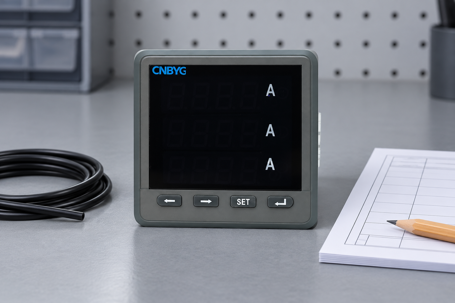
The CNBYG BY194 product page identifies RS485/MODBUS as an optional communication arrangement. Confirm the ordered variant, installed option and applicable manual before defining a test. A front photograph cannot establish terminal pinout, isolation, termination, supported diagnostics or the presence of an error counter.
When requesting assistance, provide model information, configuration records, topology, the affected segment and a small set of representative captures. Include whether the error is reported on transmitted requests or received replies and which receiver makes that judgment. Describe any changes already made and whether they were reversed after testing.
Separate the integrity question from subsequent interpretation work. Once the frame is valid, use byte and word order verification to confirm how multi-register values are decoded. Do not accept the first plausible number as proof that the integration is complete.
Close the fault with a reproducible acceptance check
Define the observation period and operating conditions before declaring success. Preserve the baseline request, number of attempted reads, successful responses, invalid frames and timeouts as separate categories. Avoid quoting a universal allowable error rate: the project must decide what data availability and quality it requires.
After an approved correction, repeat the same test conditions where practical. Confirm that the intended device responds, frames pass integrity checks, and values remain correctly interpreted. Retain the final settings and the evidence connecting the correction to the improvement. If errors persist, escalate with the original captures rather than accumulating undocumented changes.
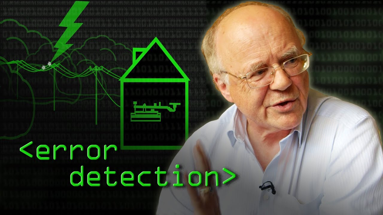
Further learning: detecting transmission errors
The educational lesson below explains the broader idea of detecting errors in transmitted data. It supports understanding why an integrity check is separate from interpreting the payload. The exact Modbus RTU algorithm and framing remain defined by the serial specification cited above, not by the video.
Frequently asked questions
Does a CRC error prove that the cable is faulty?
No. Possible causes include framing, incomplete captures, overlapping traffic, implementation issues and physical communication problems. Identify the reporting receiver and compare controlled tests before replacing hardware.
Can changing a register offset fix a CRC failure?
A register offset changes the application request. It does not repair a damaged received frame. Investigate integrity separately, then verify the offset against the exact device manual once communication is valid.
Is the RTU CRC also present in an ordinary Modbus TCP message?
Modbus TCP uses its own transport framing rather than the RTU serial frame format. A serial gateway can still report downstream RTU failures, so identify the affected segment before interpreting the error.
What should a useful fault report contain?
Include the installed variant, endpoint settings, topology, software versions, capture location, raw request and response bytes, timestamps and controlled test outcomes. Separate CRC failures from timeouts and valid exceptions.