Power Meter Modbus Setup: Communication and Data Verification
power meter Modbus setup begins with confirming the exact instrument, fitted communication option and approved register map. Match the serial settings and device address, establish a read-only connection to one documented register, then verify the decoded value against the meter display before adding more measurements. A successful reply proves communication, but does not prove that scaling, units, CT configuration or data interpretation are correct. Keep electrical installation work separate from software testing and use qualified personnel for any work on an energized measurement circuit.
This guide describes a commissioning method for compatible Modbus meters. It does not supply undocumented BY194 register addresses, factory passwords, baud rates or terminal assignments. Obtain the instructions for the exact ordered model and firmware. A product family description is a starting point, not a substitute for its communication manual.
Confirm the communication option before configuring software
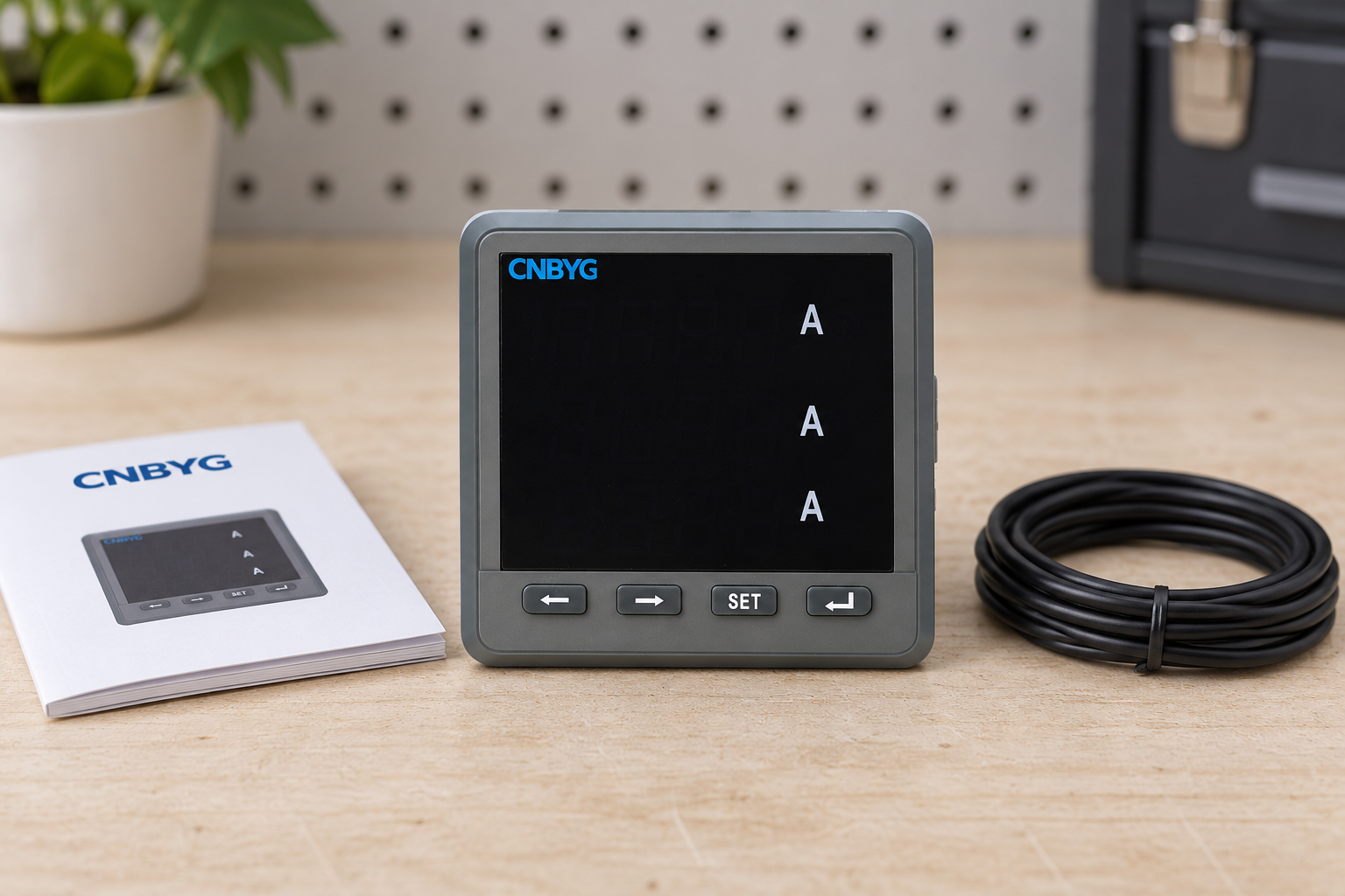
A front-panel photograph cannot establish which interfaces are fitted. Check the complete order code, label, purchase specification and manufacturer documentation. A family can include instruments with different measurement and expansion options; do not assume that every unit supports the same communications simply because the bezel looks identical.
The CNBYG BY194 series product page describes an optional digital communication function and reading transmitted data through RS-485 using MODBUS. Confirm that the supplied unit includes the required option. The public description does not establish a specific register map or guarantee every transport variant.
Distinguish serial Modbus from Modbus TCP. An RS-485 adapter does not make a serial meter an Ethernet device. A gateway may translate between interfaces, but introduces its own configuration and addressing requirements. Start with the simplest documented connection before adding a gateway, supervisory platform or remote network.
Assemble a small commissioning evidence pack
Collect the meter model, firmware where available, communication manual revision, network drawing, interface converter instructions and a list of required measurements. Record who owns changes to the instrument configuration and who approves the final supervisory tags. This prevents a software integrator from compensating silently for a measurement configuration error.
Request the register address, supported read function, register count, data type, byte or word ordering, units, scale and sign convention for each quantity. Also identify whether values are already adjusted for CT and voltage-transformer ratios. A spreadsheet containing only a display name and an address is insufficient for reliable commissioning.
The Modbus serial implementation guide hosted by SLAC distinguish the application protocol from transport and serial implementation requirements. Use the applicable documents alongside the meter manual. Protocol standards explain message structure; they cannot reveal a manufacturer’s undocumented measurement mapping.
Prepare the physical connection safely
Follow the approved terminal drawing for the supplied instrument. Keep communication conductors separate from measurement inputs and auxiliary power according to the installation instructions. Never infer an RS-485 terminal from a photograph or copy a terminal number from another model. An incorrect connection can damage equipment and create an electrical hazard.
Confirm converter compatibility, isolation requirements, cable arrangement, reference conductor guidance and the manufacturer’s shielding and termination recommendations. Do not treat all labels such as A, B, plus and minus as interchangeable across equipment vendors. Resolve the electrical signal definitions using the relevant manuals.
For an existing network, obtain its topology and authorized maintenance procedure before attaching test equipment. Adding termination or changing the signal reference without understanding the network can disrupt other devices. Inspect and test de-energized equipment where the approved procedure requires it; this article is not an instruction to access live terminals.
Match serial settings and device identity
Record the baud rate, parity, data format and stop-bit configuration specified for the meter and client. Use the documented values instead of a guessed common default. A mismatch may produce silence or invalid frames, and repeatedly changing several settings together makes the eventual cause difficult to establish.
Assign the intended device address according to the supported range and site plan. Devices sharing a serial network need an address arrangement that the controller can distinguish. Do not rely on a broadcast request to validate an individual meter; use an ordinary documented read addressed to that device.
Begin with one meter and one active client when practical and authorized. Restore the final approved network arrangement after the controlled test. Record each change so that temporary test settings do not become an undocumented production configuration.
| Setup item | Evidence to obtain | First verification | Common error to avoid |
|---|---|---|---|
| Interface option | Exact order code and fitted module | Confirm against supplied documentation | Assuming the entire family has communications |
| Serial format | Meter and client settings | Compare each configured field | Guessing a universal default |
| Device address | Approved network allocation | Read the intended individual device | Duplicate device identities |
| Register reference | Exact map and revision | Match function and addressing convention | Entering a display reference as a raw offset |
| Data representation | Type, length, ordering and scaling | Compare one decoded value with the display | Treating every pair of registers as a float |
| Measurement chain | CT and voltage ratio configuration | Check a plausible known operating condition | Applying a ratio twice |
| Failure handling | Timeout and quality policy | Disconnect or simulate lost communication safely | Displaying stale data as current |
This table is a commissioning checklist, not a list of product defaults. Every parameter must come from the actual device documentation and approved installation design.
Read one known value before building the complete tag list
Choose a documented, stable measurement that can be compared with the local display under a known operating condition. Start with a read operation and the smallest documented register group. Avoid writing configuration registers during the initial communication test; read-only verification limits unintended changes.
Record the request, response, timestamp, device identity and decoding settings. If the reply contains an exception, preserve the exception information and investigate its meaning in the protocol and device manual. Do not classify every exception as a bad cable: the device may be responding correctly to an unsupported function or invalid request.
A normal response is only the first milestone. Confirm that the returned register count matches the expected data length and that the decoded result belongs to the intended quantity. A plausible-looking number can still be a different register or an incorrectly interpreted value.
Resolve address notation explicitly
Register documentation and client software may present addresses using different conventions. A manual’s human-readable reference and the offset entered into a client are not automatically identical. Determine what the software expects and document the translation before testing many tags.
The Arduino Modbus energy meter application note is an example of integrating a specifically documented meter into a software system. Its code and mapping are specific to its example. Do not transfer those addresses into a different CNBYG instrument or assume that an example library validates another device’s configuration.
When a one-register offset appears to improve a result, verify the interpretation against the manual rather than applying an unexplained adjustment to every tag. Keep the source reference and software entry side by side in the commissioning record so a later maintainer can reproduce the decision.
Verify data type, order, units and sign
A measurement may occupy one register or several registers. Its representation can be an integer with a scale or another documented format. Read all registers required for the value using the supported operation, and apply only the ordering specified for that device and software combination.
Validate units separately from numeric decoding. A result expressed in watts must not be displayed as kilowatts without a documented conversion. Energy counters may use different units and reset behavior from instantaneous power readings. Confirm signed quantities and import/export conventions instead of interpreting every negative result as a fault.
Test more than one operating point where practical. A constant or near-zero value may conceal a decoding problem. Compare representative values with the display and other trusted measurements, accounting for update interval and normal measurement differences. Do not invent an acceptance tolerance without instrument specifications and a project requirement.
Keep CT scaling separate from communication scaling
Communications can work perfectly while the measurement chain remains wrong. Confirm sensor type, primary and secondary configuration, phase association and polarity using qualified personnel and the approved procedure. The CT selection guide explains why matching only the nominal ratio is insufficient.
Determine whether the meter publishes primary-scaled values or secondary quantities. If the instrument already applies the CT ratio, applying it again in the supervisory system produces an incorrect result. Document where each conversion occurs. A local display comparison helps, but does not independently prove the physical CT installation is correct.
Use the power meter placement guide to relate each tag to its measurement boundary. A correctly decoded feeder value cannot be treated as a whole-site value unless the electrical arrangement supports that interpretation. The portable versus fixed monitoring guide helps define which readings belong in routine monitoring and which investigations need a suitable recording instrument.
Diagnose failures in a controlled sequence
For no response, first confirm the intended device, approved connection, supported interface and matching serial configuration. Check the client and converter state before changing multiple settings. For intermittent replies, review network loading, duplicate addresses, request timing and the documented physical-layer arrangement.
For valid replies with implausible values, examine address notation, function, register length, data type, order, units and scaling. These are different fault classes from a disconnected cable. Preserve raw data while investigating so that a later decoding change can be checked against the original response.
Set request intervals and timeout behavior according to documented device and system limits. Polling as quickly as software permits can create avoidable failures. Distinguish communication quality from the measured value in the user interface: a last known number should not continue appearing as a fresh, valid reading after communication fails.
Complete handover and protect the production network
Retain the approved tag list, map revision, client settings, raw sample responses, display comparisons and measurement-chain settings. Record the final network arrangement and remove temporary test configuration. Identify who can change addresses, scaling and write permissions after commissioning.
Test restart and reconnection behavior through an authorized procedure. Confirm how missing data, stale values and restored communication are represented. If the installation supports alarms, validate the alarm against the intended quality state rather than merely checking that a number appears on a dashboard.
Traditional Modbus should not be assumed to provide user authentication or encryption by itself. The NIST operational technology security guide provides a framework for protecting industrial systems. Apply the site’s industrial network controls and avoid exposing a meter or gateway directly to an untrusted network. Communication setup does not authorize remote writes or changes to protective functions.
Further learning: how Modbus messages work
The RealPars explanation below introduces Modbus communication concepts. RealPars is an industrial education provider; this general explanation is supplementary and does not supply CNBYG-specific defaults, register addresses or installation approval.
Watch How does Modbus Communication Protocol Work?
Frequently asked questions
Can I use a register map from another power meter?
No. Obtain the map for the exact model and applicable revision. Similar display appearance or a shared Modbus interface does not establish identical addresses, scaling or supported functions.
Does a successful read prove the displayed engineering value is correct?
No. Verify address notation, data type, ordering, units and scaling, then compare representative results with the display and approved measurement evidence. Communication success and measurement accuracy are separate checks.
What baud rate should I use for a BY194 meter?
Use the supplied model’s documentation and approved network settings. This guide does not establish a universal factory baud rate or claim that every BY194 option uses identical communication parameters.
Why does the supervisory value differ by a constant multiplier?
Investigate units, documented register scale and where CT or voltage ratios are applied. Do not insert a corrective multiplier until the source of the difference is established and recorded.
For the related measurement workflow, see our guide to energy counter rollover and data continuity.
For the related measurement workflow, see our guide to Modbus byte and word order verification.
For the related measurement workflow, see our guide to RS485 termination and cable-end checks.
For the related measurement workflow, see our guide to meter polling intervals and data freshness.
For the related measurement workflow, see our guide to Modbus register address offset verification.
For the related measurement workflow, see our guide to power meter network security boundaries.
For the related measurement workflow, see our guide to floating-point precision and finite reading limits.
For the related measurement workflow, see our guide to Modbus exception response diagnosis.
For the related measurement workflow, see our guide to Modbus CRC integrity troubleshooting.
For the related measurement workflow, see our guide to invalid and nonfinite meter readings.
For the related measurement workflow, see our guide to meter configuration backup and replacement checks.
For the related measurement workflow, see our guide to coherent multi-register readings.
For the related measurement workflow, see our guide to gateway cache freshness verification.
For the related measurement workflow, see our guide to RS485 galvanic isolation.
For the related measurement workflow, see our guide to register map revision compatibility.
For the related measurement workflow, see our guide to measurement data quality mapping.
For the related measurement workflow, see our guide to read-only access acceptance testing.
For a related engineering workflow, see Power Meter Alarm Hysteresis: Set and Test Application Deadbands.
For a related engineering workflow, see Power Meter Unit Normalization: Prevent kW and MW Mapping Errors.
For a related engineering workflow, see Power Meter Asset Mapping: Verify Physical and Gateway Identity.
For a related engineering workflow, see Modbus Diagnostic Logs: Capture Useful Request and Response Evidence.
For a related engineering workflow, see Power Meter Historian Retention: Keep Useful Energy Evidence.
For a related engineering workflow, see Modbus RTU Multiple Masters: Resolve Serial Bus Ownership.
For a related engineering workflow, see Power Meter CSV Import: Validate Decimal Separators and Units.
For a related engineering workflow, see Duplicate Energy Meter Records: Reconcile Intervals Without Double Counting.
For a related engineering workflow, see Modbus Broadcast Address 0: Why Silence Does Not Prove Failure.
For a related engineering workflow, see Power Meter Firmware Updates: Build a Regression Acceptance Plan.
For a related engineering workflow, see Power Meter Decommissioning: Preserve Data and Close Collection Paths.
For a related engineering workflow, see Temporary Meter Maintenance Access: Revocation and Closeout Checks.
For a related engineering workflow, see Energy Historian Backup Restore Acceptance Test: Evidence and Checklist.
For a related engineering workflow, see Industrial Meter Diagnostic Log Redaction: A Support Handover Checklist.
For a related engineering workflow, see Power Meter Export File Integrity: Checksum Verification and Limits.
For a related engineering workflow, see Energy Meter Interval Beginning or Ending Timestamps: How to Verify.
For a related engineering workflow, see Power Meter CSV Header Encoding: UTF-8 and Import Validation.
For a related engineering workflow, see Power Meter Replacement Compatibility Checklist: Approving a Spare Unit.
For a related engineering workflow, see Power Meter Commissioning Witness Records: Scope, Evidence and Sign-Off.
For a related engineering workflow, see Meter and Gateway Configuration Ownership: A Practical Handover Guide.