CT Selection for Multifunction Power Meters
CT selection for a power meter starts with the meter’s exact current-input specification, followed by the primary-current range, required measurement accuracy, secondary-circuit burden, and installation conditions. A matching ratio alone does not establish compatibility. Specify the CT and meter as one measurement chain, including cable length, polarity, scaling, and commissioning checks. This guide focuses on selecting conventional current transformers for multifunction panel metering. Low-power sensors and flexible coils require their own supported inputs and instructions. It does not assume that an ordinary panel meter provides billing-grade accuracy, specialist harmonic recording, or a particular input solely because its product photograph looks familiar.
Identify the exact meter and input first
Obtain the model code, current-input rating, input burden, terminal arrangement, configuration instructions, and manufacturer-approved sensor types. Different versions of a product family may accept different signals. A conventional current-output CT cannot be substituted automatically for a voltage-output sensor, and neither can be treated as a flexible coil without the appropriate interface.
Confirm how the meter expresses CT scaling. Some interfaces request primary and secondary values; others request a ratio or multiplier. Record the required format and who will enter it. An otherwise suitable CT can produce incorrect reported current, power, and energy if the scaling is wrong. The commissioning record should show both the physical CT label and the stored meter settings.
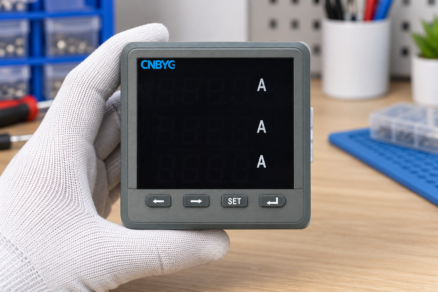
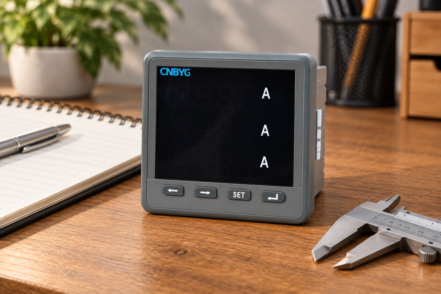
The BY194 series multifunctional power instrument provides the product context for this discussion. Verify the selected variant’s manual before specifying inputs or accuracy. The illustration shows an ordinary unpowered panel instrument and does not identify a particular CT, certify the complete measurement chain, or prove harmonic-analysis capability.
Define the primary-current operating range
Start with the feeder design, expected normal load, minimum load of interest, permissible operating peaks, and any planned expansion. The CT’s rated primary current should suit that range while retaining useful performance at the lower currents that matter to the task. Selecting a greatly oversized ratio simply to cover an uncertain future can reduce useful secondary signal during today’s light loading.
Separate continuous operation from short-duration events. A CT rating suitable for the expected maximum normal load does not by itself establish performance during faults or motor starting. Record the purpose of the measurement and the events that must be captured. If a specialist recording function is required, evaluate sensor and recorder performance for that function rather than assuming a normal metering specification covers it.
Use verified operating data where available. Existing metering, equipment schedules, and a representative survey can reduce uncertainty. Nameplate totals may overstate simultaneous demand, while a single quiet-shift observation can understate it. Document the basis for the selected ratio and the conditions not yet measured.
Match primary and secondary ratings
For a conventional CT, the nominal ratio relates rated primary and secondary current. As an illustrative arithmetic example, a 400/5 A ratio corresponds to a multiplier of 80. A secondary current of 2 A would nominally correspond to 160 A primary. This example is a scaling calculation, not a CNBYG product specification or an accuracy guarantee at that operating point.
Check the meter’s supported secondary rating before using that example. Do not configure a meter for a different secondary value merely to make the display look plausible. Where a device requires a dedicated sensor interface, use its specified conversion rather than a conventional current-transformer ratio. Verify whether the software has already applied the multiplier before multiplying exported data again.
Choose the ratio together with the performance requirements. Two CTs with the same nominal ratio can have different accuracy, burden capability, physical openings, and installation ratings. Keep those properties as separate fields in the purchase specification so that an apparently similar substitute cannot bypass the requirements.
Estimate the complete secondary burden
The secondary circuit includes the meter input, connecting leads, and relevant connection resistance. Obtain the meter’s specified burden and estimate the loop resistance using the actual cable route and conductor properties. Use total outgoing-and-return path length where appropriate; overlooking the return conductor can materially understate the cable contribution.
For a predominantly resistive lead circuit, its contribution can be estimated from apparent power as approximately I squared times R, where I is the relevant secondary RMS current and R is the loop resistance. The result has units of VA in this simplified calculation. Actual devices can have reactive components, so combine the circuit requirements using the manufacturer’s method rather than treating every burden as a pure resistor.
For illustration, a 0.2-ohm resistive loop contributes approximately 5 VA at 5 A, because 5 squared multiplied by 0.2 equals 5. At 1 A, the same loop contributes approximately 0.2 VA. These are arithmetic examples using an assumed resistance, not recommended cable dimensions or CT ratings. They show why lead burden must be evaluated at the specified secondary current.
Compare the complete burden with the conditions under which the proposed CT’s accuracy is specified. A burden below a maximum label does not automatically prove the required accuracy throughout the operating range. Ask for the relevant performance evidence and the permitted burden range. Recalculate when cable length, conductor size, or connected devices change.
Choose accuracy for the actual measurement task
State whether the installation needs process indication, energy management, comparative load analysis, regulated metering, or another purpose. These tasks can have different acceptance requirements. A convenient accuracy-class label is insufficient without its applicable current range, burden conditions, and the rest of the measurement chain.
The IEC 61869-2 publication overview identifies requirements for inductive current transformers used with measuring or protective equipment. Consult the applicable full standard and the supplier’s documented performance for procurement. A standards reference in a quotation does not independently establish that the supplied CT and installed circuit meet the required conditions.
Keep metering and protection duties distinct. A CT selected for relay behavior during abnormal conditions is not automatically the right choice for accurate low-load energy measurement. If one installation requires both functions, have the design specify how each requirement is met. Do not share a secondary circuit or add devices without assessing burden, safety, and the approved design.
For specialist power-quality recording, the IEC 61000-4-30 publication overview helps identify a different measurement-method context. An ordinary panel-meter and CT combination should not be described as meeting specialist measurement requirements without evidence for the complete arrangement.
Check mechanical and installation compatibility
Confirm the conductor dimensions, number of conductors passing through the opening, available space, mounting method, insulation requirements, and environmental conditions. A CT that fits the current range but cannot be installed correctly is unsuitable. Review physical dimensions against the real panel, not just a catalogue photograph.
Consider whether the installation can be isolated and whether a solid-core or split-core arrangement is appropriate to the approved work method. Split-core convenience does not remove the need to check performance, closure, mounting, and electrical ratings. Neither construction authorizes work on accessible live conductors.
Verify thermal and short-time requirements through the electrical design and supplier documentation. The selection must suit the actual system and installation conditions. Do not invent a fault rating from the normal primary-current ratio. Qualified personnel must follow the manufacturer’s handling instructions and the site’s electrical safety procedure.
Use a purchase and design checklist
This table organizes information that should be supplied or verified. It does not prescribe universal numeric ratings or claim that every meter accepts the same sensor.
| Requirement | Information to obtain | Acceptance question |
|---|---|---|
| Meter interface | Exact input type and supported secondary rating | Does this CT output match this meter variant? |
| Operating range | Minimum useful load, normal demand, and relevant peaks | Is documented performance adequate where measurements matter? |
| Ratio configuration | CT label and meter scaling format | Can the setting be entered and independently checked? |
| Secondary burden | Input burden, lead loop, connections, and other devices | Does the installed circuit meet the stated accuracy conditions? |
| Accuracy purpose | Required measurement task and performance evidence | Is the entire chain suitable rather than just one component? |
| Physical installation | Opening, mounting, insulation, and environment | Can it be fitted safely under the approved design? |
| Commissioning | Phase assignment, polarity, scaling, and reference checks | Will the completed record reveal common installation errors? |
Include the applicable standard edition and supplier evidence in the purchase documents. Keep substitutions subject to review of these requirements. A different CT with the same ratio is a design change if its interface, burden, accuracy, or installation properties differ.
Protect the secondary circuit and verify polarity
Conventional current-output CTs must not have their secondary opened while primary current flows. The work method must provide approved handling and isolation arrangements for installation, testing, or instrument replacement. Do not improvise terminal disconnection as a troubleshooting step. Where required, use the designed shorting facilities and follow the manufacturer’s procedure.
Record primary and secondary polarity markings and connect the channels according to the approved drawing. Pair each current channel with the correct voltage phase. A reversed or mismatched channel can distort power and power-factor interpretation even when current magnitudes appear reasonable. Check the complete measurement arrangement before attributing a surprising reading to the loads.
Use an expected operating condition to verify phase relationships and sign conventions. Imported and exported power conventions can differ between instruments and software. The commissioning report should state the convention used rather than changing polarity solely to force a preferred sign on the display.
Commission with traceable checks
Compare configured ratio settings with the installed labels. Verify channel names, conductor identity, polarity, and time synchronization where records are compared. Confirm that the meter and exported data apply the multiplier once. Review current readings at representative loads, including a lower-load condition if that is important to the project.
Keep the instrument settings, CT information, cable route, reference instrument details, and acceptance results together. A reported agreement at one current does not prove accuracy at every current, burden, or frequency. State the scope of the check and remaining limitations so later users do not overinterpret the result.
For survey planning, see the power quality survey guide. For installation boundaries, see the power quality meter placement guide. For a separate diagnostic task, see the harmonic spectrum interpretation guide; suitable harmonic recording requires its own verified sensor and instrument capabilities.
Further learning: measurement and monitoring context
This NPTEL lecture introduces the broader standards and monitoring context. It supports the purpose of a measurement specification and does not replace a CT manual, an instrument connection diagram, or a commissioning procedure.
Watch Power Quality: Standards and Monitoring
For a complementary engineering check, see setting up power meter Modbus communication.
Frequently asked questions
Is the CT ratio enough to select a replacement?
No. Verify the meter interface, secondary rating, accuracy conditions, burden, physical opening, mounting, and installation ratings. A matching nominal ratio does not show that the replacement will meet the existing measurement requirements.
Can a higher ratio improve measurement accuracy?
A higher ratio is not an automatic accuracy improvement. It changes the secondary signal at a given load and must suit the required operating range. Use documented performance at the minimum and normal currents that matter to the task.
Why must cable length be included in the burden calculation?
The secondary leads contribute impedance to the measurement circuit. Include the full relevant loop and the meter input when assessing the CT’s specified performance conditions. Recheck the calculation after changing cable length, conductor size, or connected devices.
Does an ordinary meter photograph prove a five-amp CT input?
No. A photograph shows visible product identity and exterior features. Obtain the exact model’s input specification and instructions before selecting or connecting a CT. Never infer the supported signal type from the instrument’s appearance.
For a related metering task, see our guide to current-transformer open-secondary hazards during meter replacement.
For the related measurement workflow, see our guide to current transformer burden calculation.
For the related measurement workflow, see our guide to phase sequence and measurement-channel checks.