RS485 Meter Galvanic Isolation: Ground Potential and Verification
RS485 galvanic isolation separates the electrical reference of a communication interface from another circuit while allowing information to cross the boundary. In an industrial meter network, its main value is controlling the effects of ground potential differences and unwanted current paths. Differential signalling alone does not provide this separation. Before specifying an isolated interface, identify the two circuits that need separation, verify both signal and power paths, and obtain the exact model documentation. An RS485 label, a successful Modbus reply, or an insulated enclosure does not prove that a port is galvanically isolated.
This guide helps panel builders and integration engineers review the isolation requirement for a meter connection. It does not provide a terminal diagram, insulation test voltage or a safe working voltage for any CNBYG instrument. Electrical inspection and testing require qualified personnel, the approved site procedure and equipment suitable for the installation.
Why a differential interface still needs a reference review
An RS485 receiver interprets the difference between its two data conductors. That helps reject certain disturbances affecting both conductors similarly, but the input circuitry still has limits relative to its own local reference. When equipment at opposite ends of a cable sits at different potentials, a small differential signal can coexist with an unacceptable common-mode condition. Cable length is only one influence; cabinet bonding, power supplies, surge exposure and connected equipment also matter.
The Texas Instruments RS485 Design Guide explains the distinction between differential signalling, common-mode limits and grounding considerations. Its interface examples describe general design principles. They are not evidence that a specific meter contains an isolated transceiver or that the same component limits apply to a complete installed instrument.
A practical review starts with the full route: meter, communication cable, converter, gateway, computer and any auxiliary power source. A connection that appears separate at the meter can become connected through a grounded USB adapter or shared supply elsewhere. Document those paths before deciding which device should provide the boundary.
Define exactly what is being isolated
The phrase isolated meter can refer to different things. Measurement inputs may be separated from an internal circuit; the supply may have an isolation barrier; the communication port may be isolated; or several interfaces may share a reference. These descriptions cannot be exchanged. Ask which terminals and circuits the manufacturer places on each side of the stated barrier.
A communication isolator also needs a suitable power arrangement. Passing data through an isolating element while powering both sides from an inappropriate shared reference can defeat the intended system separation. Conversely, an isolated supply alone does not establish separation of the data path. Both must be reviewed as one design.
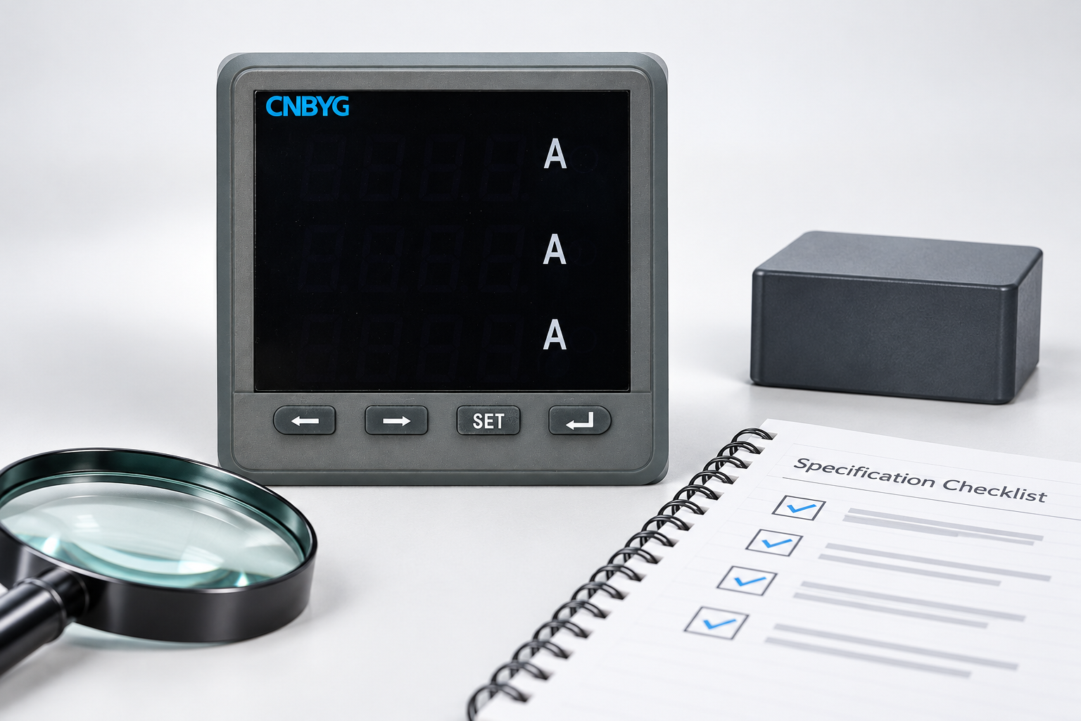
Use the following evidence checklist during specification. It is a qualitative review aid, not a substitute for the equipment documentation or the applicable electrical safety assessment.
| Review item | Evidence to request | Reason it matters |
|---|---|---|
| Boundary location | Diagram naming the circuits on each side | Prevents confusing supply, input and port isolation |
| Fitted option | Order code and installed-interface confirmation | A family option may not be fitted to every instrument |
| Signal path | Interface specification for the actual assembly | Data conductors must cross the intended boundary correctly |
| Power path | Supply and reference arrangement | Shared supplies can introduce an unintended connection |
| Shield and bonding | Approved installation drawing | Shield treatment must fit the site bonding design |
| Ratings | Working conditions and documented test classification | A short test rating is not a continuous operating allowance |
| Other equipment | Converter, gateway and service-tool details | A separate interface may bridge the boundary |
Keep isolation separate from termination and biasing
Termination addresses transmission-line behaviour at cable ends. Biasing establishes an intended idle-state condition where required by the design. Galvanic isolation addresses an electrical separation boundary. Each has a different purpose, so a resistor change cannot be assumed to solve a ground potential problem, and adding an isolator cannot be assumed to fix an incorrectly terminated network.
Review the existing RS485 termination guide when reflections, cable-end placement or idle behaviour are under investigation. Record those findings separately from the isolation review. If several changes are made together and communication improves, the team loses the ability to explain which change resolved the problem.
A useful fault record distinguishes what is observed from what is inferred. For example, repeated reply failures during operation of a nearby machine are an observation. Ground potential difference is one possible explanation, alongside interference, supply disturbance, incorrect cabling or a failing interface. Treat isolation as a design question to verify, not a label to attach to every intermittent communication fault.
Review the installation without creating a new current path
Start with drawings, part numbers and accessible labels. Identify cabinet locations, supply sources, reference connections and approved bonding points. Review service-tool connections before attaching a laptop or converter. A test adapter can change the very condition being investigated by adding a connection through its supply or protective earth.
Do not disconnect protective conductors, remove required bonding or improvise a floating supply to make communication work. Do not apply an insulation-resistance tester across a communication port unless the exact equipment instructions explicitly permit that procedure. A generic insulation test can damage electronic interfaces even when the equipment contains a correctly designed barrier.
If measurements of reference potentials are necessary, the responsible electrical team must define the method, instrument category, access arrangements and permitted operating conditions. This article deliberately gives no live-terminal probing sequence. The objective is to build an evidence package that a qualified engineer can use to evaluate the interface safely.
Verify communication after the boundary is established
Once the electrical design has been approved, perform a controlled functional check using the intended converter and power arrangement. Begin with one known device and a documented read operation. Confirm the address, serial settings and register interpretation, then compare a stable measurement against an independent or local indication as permitted by the instrument documentation.
The meter Modbus setup workflow covers the communication sequence. A correct response establishes that the selected route works under the tested conditions. It does not measure insulation performance, prove a safety classification or establish immunity to every disturbance the installation may encounter.
Capture the test duration, operating state, request count, successful replies and error events. Include a normal production condition if it can be tested safely. Avoid deliberately introducing hazardous ground differences or fault voltages. Laboratory compliance testing and field communication acceptance have different purposes and require different methods.
Example: two cabinets and one service laptop
Consider a meter in a motor-control cabinet connected to a gateway in a separate control cabinet. Communication is stable with the installed gateway but becomes intermittent when a service laptop and temporary USB converter are connected. It is tempting to replace the meter immediately. A more useful first step is to compare the temporary route with the approved route.
The review might find different converter isolation, a different supply source, altered reference connections or a second active client. These are possibilities to inspect, not a diagnosis of this hypothetical installation. Record the temporary adapter model, laptop power state and connection arrangement, then restore the approved setup before drawing conclusions.
If an interface change is proposed, define acceptance before purchasing it: the required boundary, the supported communication format, environmental conditions, installation space, power needs and the evidence needed for the site assessment. A higher advertised test voltage alone is an incomplete selection criterion. Compatibility must cover the whole installed assembly.
What to ask CNBYG before ordering
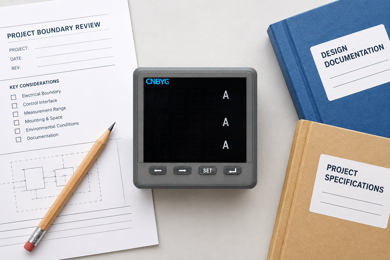
The BY194 Series Multifunctional Power Instruments product page identifies the meter family and describes optional RS485/MODBUS communication. That public description does not establish the isolation arrangement of the exact unit being selected. Request the complete order code, applicable manual and a written explanation of the communication option.
Provide the supplier with the system drawing, gateway type, cable route, supply arrangements and intended installation environment. Ask which interfaces share a reference, whether the offered port is isolated, and what the documented ratings mean under the proposed conditions. Obtain the installation drawing for the selected variant rather than copying terminal assignments from a photograph of a similar instrument.
For the measurement side of the project, keep the multifunction meter wiring review as a separate workstream. A communication isolator does not replace correct measurement wiring, CT handling, circuit protection or the installation requirements of the meter itself.
Keep a traceable isolation acceptance record
Store the approved drawing, actual installed part numbers, supplier statements and functional test results together. Include any restrictions such as permitted supplies, shield treatment or service-tool requirements. These records let a replacement engineer preserve the intended boundary rather than unintentionally changing it during maintenance.
The NIST Guide to Operational Technology Security supports disciplined asset records and configuration management in operational systems. It is used here for documentation practice, not as a source of electrical isolation ratings. Keep those ratings tied to the actual equipment documentation and the site engineering assessment.
Set a review trigger when a gateway, converter, supply or cabinet connection changes. The meter may remain untouched while the system boundary changes around it. This is why the final record should describe the route and its assumptions, instead of merely stating isolation checked.
Educational background: transferring a signal across a barrier
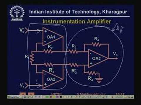
NPTEL’s Signal Conditioning lecture discusses isolation amplifiers and the distinction between transferring information and sharing a direct electrical connection. It provides background for understanding an isolation boundary; it is not a BY194 installation tutorial or proof of any fitted interface.
Frequently asked questions
Does every RS485 meter have galvanic isolation?
No. RS485 identifies a signalling interface, not a guaranteed isolation arrangement. Verify the exact meter option, interface documentation and circuits separated by the stated barrier.
Will an isolated converter fix all Modbus errors?
No. Addressing, serial settings, cable topology, termination, interference and software interpretation can also cause problems. Diagnose those separately and test the approved configuration under documented conditions.
Can I test port isolation with a general insulation tester?
Only use a procedure explicitly permitted for the exact instrument. Applying an unsuitable insulation test across electronic communication terminals can damage the interface and does not provide a valid acceptance result.
Is a successful read proof that the isolation rating is adequate?
No. It demonstrates functional communication in the tested arrangement. Isolation ratings and installation suitability require the applicable equipment evidence and electrical assessment.