Voltage Unbalance Calculation: Three-Phase Meter Checks
Voltage unbalance calculation begins with three line-to-line voltage measurements taken at the same electrical point under the same operating condition. For the maximum-deviation method, calculate their average, find the largest absolute difference from that average, divide by the average and multiply by 100. Record the method alongside the percentage. A meter’s negative-sequence voltage-unbalance reading uses a different definition and cannot be assumed to equal a calculation based only on the three RMS magnitudes. The measurement location, timing and instrument configuration matter as much as the arithmetic.
This guide is for engineers reviewing three-phase meter records and investigating an uneven supply. It does not provide a live testing procedure. Access to electrical circuits, instrument connection and any changes to energized equipment require qualified personnel and the site’s approved safety arrangements.
Choose the voltage-unbalance definition first
The maximum-deviation method compares line-voltage magnitudes. If the measurements are Vab, Vbc and Vca, their average is the sum divided by three. The largest absolute difference from the average becomes the numerator of the calculation. This method can be useful for motor-system screening when used with the relevant guidance and limitations.
A sequence-component method instead compares negative-sequence and positive-sequence voltage components. Those components depend on the phase relationships as well as magnitudes. Three rounded RMS values alone do not contain enough information to reconstruct every detail of that measurement. A report should state which method it uses rather than simply labelling the result unbalance percent.
The U.S. Department of Energy motor-systems tip sheet presents the maximum-deviation approach. The NPTEL power-system analysis material on symmetrical components gives background on resolving unbalanced systems into sequence components. These sources serve different purposes; they should not be used to claim that the two metrics are interchangeable.
Calculate from three simultaneous line voltages
Use this expression for the maximum-deviation method:
Average voltage, Vavg = (Vab + Vbc + Vca) / 3
Voltage unbalance, % = 100 × max(|Vab − Vavg|, |Vbc − Vavg|, |Vca − Vavg|) / Vavg
All three inputs must use the same unit and the same measurement basis. Do not mix line-to-neutral readings with line-to-line readings. Do not combine one phase from yesterday with two phases from today’s shift. A zero or missing input is an invalid dataset for routine screening, not evidence of an unusually high but trustworthy calculated percentage.
Suppose an illustrative record contains 398 V, 402 V and 400 V. The average is 400 V. The absolute deviations are 2 V, 2 V and 0 V, so the largest is 2 V. The result is 100 × 2 / 400 = 0.5%. This is a worked arithmetic example, not a measurement taken at a CNBYG installation.
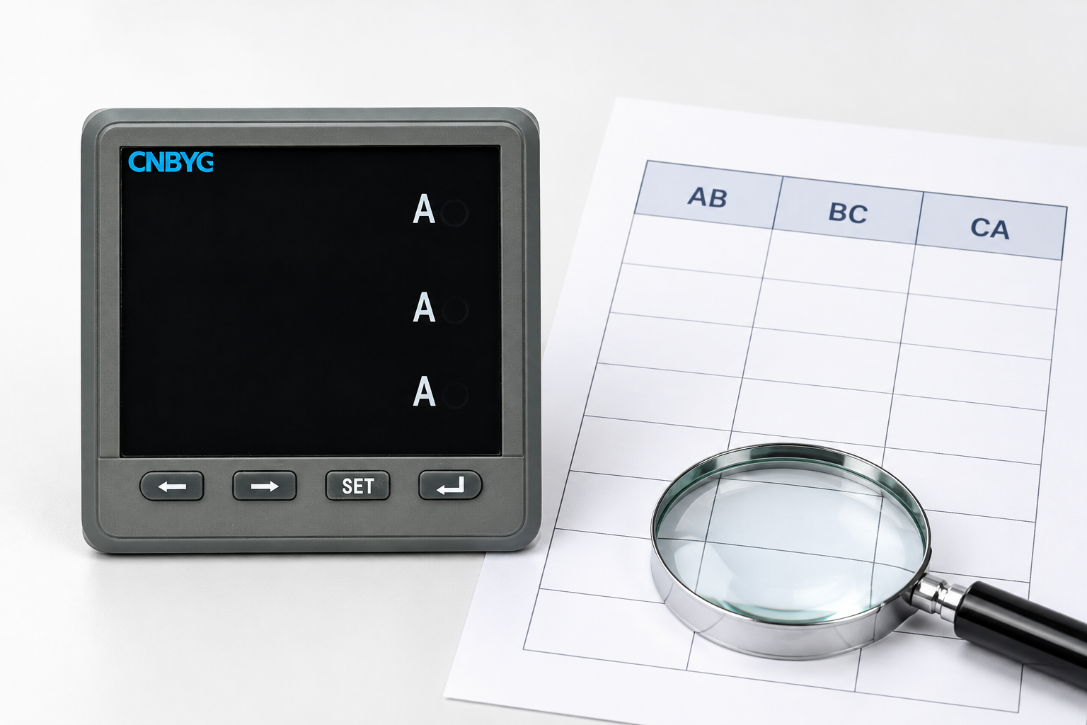
| Line pair | Illustrative RMS voltage | Absolute deviation from 400 V average |
|---|---|---|
| AB | 398 V | 2 V |
| BC | 402 V | 2 V |
| CA | 400 V | 0 V |
| Calculated result | Average 400 V | Maximum-deviation unbalance 0.5% |
The formula follows the DOE method linked above. Keep additional decimal places during intermediate calculations and round the final result consistently with the input precision. Excessive displayed digits do not improve the underlying measurement accuracy.
Separate unbalance from voltage level and phase sequence
A supply can have three equal voltages that are all below the intended operating range. Its magnitude-unbalance result can be small even though the voltage level needs attention. Conversely, a reasonable average voltage can conceal a meaningful difference between individual lines. Review the absolute voltages and the unbalance metric together.
Phase sequence is another separate issue. Correct phase order does not establish balanced voltage magnitudes. A magnitude calculation also does not confirm the intended rotation. The meter phase-sequence guide explains that verification task and why the evidence should be kept distinct.
Likewise, a high current imbalance does not by itself identify the voltage-unbalance percentage. Motor characteristics, single-phase loading and other circuit conditions can make current behaviour differ substantially from voltage behaviour. Record voltage and current findings separately, then interpret them with the actual load and equipment requirements.
Confirm that the meter record represents one condition
A monitoring system may poll registers one at a time. If the load changes between requests, the resulting row can combine measurements from different moments. Before calculating a three-value metric, establish how the meter updates its measurements and how the acquisition system groups them.
The coherent register-read guide covers the difference between successful data transfer and a consistent measurement snapshot. Reading several values in one request does not automatically prove simultaneous acquisition inside the instrument. Obtain the exact documentation for update and snapshot behaviour when the application depends on that distinction.
Record timestamps, averaging periods and data-quality status. Reject a row containing a stale phase, failed read or undocumented substitution. A software dashboard may continue to display the last good value after a communication loss; that value must not silently become part of a fresh unbalance calculation.
Check configuration before declaring a supply fault
Verify that the three values come from the intended circuit and voltage mode. Incorrect phase assignments, mismatched transformer ratios or an unsuitable system configuration can produce misleading comparisons. A software label such as AB does not prove which physical inputs produced the value.
For systems using voltage transformers, review the voltage-transformer ratio verification guide. Apply the documented ratio consistently and confirm whether the meter already reports primary-scaled quantities. Reapplying a multiplier in software can distort the records used for investigation.
If one value changes after a configuration update, preserve both the old and new configuration records. Do not interpret the difference as a physical improvement until measurement consistency has been checked. The correct comparison uses the same method, location and scaling with a known configuration history.
Interpret motor guidance within its scope
The DOE motor-systems tip sheet discusses the adverse effects of voltage unbalance on three-phase motors and recommends keeping unbalance at motor terminals below 1%. Treat that as motor-oriented guidance from the cited publication. It is not a universal alarm threshold for every electrical device or every measurement method.
An assessment near a decision threshold needs the equipment manufacturer’s current instructions, the applicable standard and measurement uncertainty. A value slightly below a threshold is not automatically acceptable when input accuracy, rounding or timing could change the classification. A value above it calls for engineering review rather than an improvised equipment setting.
The same publication describes possible effects such as increased losses, heating and current unbalance. It does not justify calculating a precise temperature rise or lifetime reduction for an arbitrary motor from one percentage. Such a prediction needs the motor design, loading, operating history and supporting evidence.
Investigate patterns across locations and operating states
Begin with the existing approved monitoring data. Compare the main supply point with downstream measurements taken over compatible periods. A condition present upstream and downstream suggests a different investigation boundary from a condition seen only at one branch. This is a way to organise evidence, not a conclusion about responsibility for a fault.
Note when the pattern appears: one shift, a large single-phase load, a transformer tap change, capacitor switching or a particular production state. The DOE material identifies several possible causes, but those possibilities must be checked against the actual installation. Do not assume that adding compensation equipment will correct every uneven voltage condition.
Any physical inspection or electrical measurement should be planned by the qualified team. Keep the request specific: location, operating state, observed trend, calculation method and the decision that the evidence is meant to support. This makes an investigation more useful than forwarding a screenshot labelled bad phase.
Specify the right meter capability for ongoing monitoring
The BY194 multifunctional instrument product page identifies the product family. It does not establish that every variant measures the required three voltages, calculates a sequence-based unbalance metric or stores event records. Request those capabilities explicitly for the exact order code.
State the electrical system, voltage connection mode, measurement location, required accuracy, averaging window and reporting interface. If the project needs an instrument-calculated unbalance value, ask for the definition and register description. If the project will calculate the value in software, confirm that the available voltage data and timing are suitable for that method.
The three-phase power-meter overview supports the broader selection discussion. For this particular application, a clearly documented measurement method is more useful than an unexplained percentage on a display. Specify the evidence that the commissioning team will need before the instrument is ordered.
Keep an investigation record that can be repeated
Save the original three readings, their units, timestamps, calculation expression and unrounded result. Include meter identity, firmware or configuration revision, scaling and the circuit location. Mark rejected rows and explain why they were excluded. Do not silently fill a missing phase with its previous value.
After a corrective action, compare similar production conditions and a suitable observation period. One improved snapshot may not represent the full operating cycle. A repeated trend with the same calculation basis gives the engineer stronger evidence that the condition changed.
Set separate outcomes for data quality and electrical assessment. First establish that the records are trustworthy. Then let the responsible engineer decide whether the measured condition meets the equipment and site requirements. This keeps an integration correction from being mistaken for a verified electrical repair.
Educational background: three-phase systems
NPTEL’s Three Phase System lecture provides background on phase relationships and three-phase quantities. It helps explain why the measurement basis matters. It is not a site troubleshooting procedure and does not define a BY194-specific unbalance function.

Frequently asked questions
Can I calculate voltage unbalance from three line voltages?
Yes, the maximum-deviation method uses three corresponding line-to-line RMS voltages. Their timing, measurement basis and location must be consistent, and the report must name the calculation method.
Is that the same as negative-sequence voltage unbalance?
No. The sequence-component method also depends on phase relationships. Do not compare its percentage directly with a magnitude-only result without checking the instrument definitions.
Does a small unbalance percentage prove the supply voltage is correct?
No. Three equally low or high voltages can produce a small unbalance percentage. Check individual voltage levels, operating limits and the unbalance metric separately.
Can every BY194 variant calculate unbalance automatically?
Do not assume that. Confirm the exact variant’s available voltage measurements, calculation definitions, timing and communication registers before specifying the monitoring method.