Power Meter Voltage Transformer Ratio: Primary Values, Scaling and Checks
A power meter voltage transformer ratio converts the voltage at a compatible instrument’s input into the voltage at the measurement point. Calculate the ratio from the transformer’s declared primary and secondary voltages, using the same voltage basis on both sides. Then confirm where scaling occurs: inside the meter, in a gateway, or in reporting software. Applying the same multiplier twice can produce convincing but incorrect voltage, power and energy records. This guide explains the calculation and the checks required before accepting a primary-side result; it does not provide settings for an undocumented meter model.
Establish whether a voltage transformer is actually installed
Start with the approved single-line diagram and the installed equipment schedule. A voltage transformer, also called a potential transformer or VT/PT, supplies a reduced voltage to an appropriate measurement circuit. Some installations connect an appropriately rated meter directly to the circuit instead. The two arrangements require different configuration, protection and verification. Never choose a ratio merely because a familiar number appears in an old commissioning spreadsheet.
The LibreTexts lesson on special transformers explains voltage transformation and how instrument-transformer multipliers relate to secondary measurements. Use that principle alongside the exact transformer and instrument documents. The lesson’s example equipment does not establish the permissible input voltage or terminal arrangement of a CNBYG instrument.
For the wider installation workflow, use the multifunction power meter wiring guide. Keep installation review separate from arithmetic: a mathematically correct ratio does not establish that the input circuit is safe or that the selected instrument is compatible.
Read the nameplate on a consistent voltage basis
Record the primary voltage, secondary voltage, winding arrangement, selected tap and intended measurement connection. Identify whether the stated voltages refer to line-to-line quantities or individual phase windings. A three-phase nameplate may express winding voltages using a square-root-of-three notation. Preserve that notation in the worksheet rather than removing it without understanding the connection.
The calculation requires comparable quantities. If both declared winding voltages contain the same square-root-of-three divisor, it cancels in the ratio. If one value is line-to-line and the other is phase-to-neutral, dividing the two without conversion introduces a systematic error. Confirm the basis from the transformer diagram and meter instructions; do not resolve uncertainty by selecting whichever setting makes the display look familiar.
Nameplate photographs, approved drawings and manual revisions should remain attached to the record. A ratio written on a panel door may describe an earlier transformer, a different tap or a billing multiplier that includes current transformation. Check the physical installation against the current documentation before using it as evidence.
Calculate the ratio and retain units
For compatible primary and secondary voltage definitions, the dimensionless voltage ratio is:
Kᵥ = Vprimary / Vsecondary
The corresponding primary voltage is Vprimary = Kᵥ × Vsecondary. Convert kilovolts into volts before dividing. As an illustrative arithmetic example, a transformer declared as 11,000 V to 110 V has a ratio of 100. A measured secondary value of 108 V would correspond nominally to 10,800 V on that same voltage basis, before considering transformer and instrument measurement errors.
These numbers demonstrate scaling only. They are not recommended CNBYG input ratings, a transformer selection or a permission to connect an instrument to that circuit. The installed secondary rating, burden, accuracy requirements, protection and wiring arrangement must all be appropriate for the actual project.
Where a meter asks for primary and secondary values separately, enter the documented quantities in its required units. Where it asks for a single factor, enter the ratio in the format specified by its manual. A field labelled PT primary may expect volts, kilovolts or a value accompanied by a separate unit selection. Screen labels alone are insufficient evidence.
Separate voltage scaling from current scaling
A current transformer has its own ratio. For a simplified measurement chain where both raw voltage and raw current remain secondary quantities, primary power and energy scaling involves both ratios. With illustrative factors Kᵥ = 100 and Kᵢ = 40, their product is 4,000. A secondary-side accumulated energy of 2 kWh would then correspond to 8,000 kWh, provided the register is genuinely unscaled and represents the same energy quantity and interval.
The same voltage and current scaling relationships determine the combined multiplier for a defined secondary power measurement. Modern digital instruments may already apply one or both factors internally. Consequently, the product of the ratios is a calculation rule for a defined measurement chain, not an instruction to multiply every downloaded kWh register.
Use the separate CT selection guide when assessing current inputs. Changing a VT setting cannot correct a CT polarity problem, an incompatible current input or a voltage/current phase mismatch. Document each part of the chain independently.
Determine where each displayed value is scaled
List every value used by operators: the local voltage display, a communicated voltage register, instantaneous kW, cumulative kWh and the final dashboard tag. Ask whether each is a primary quantity, a secondary quantity or a raw integer accompanied by a decimal scale. The answer can differ among registers on the same instrument.
The power meter Modbus setup guide covers register decoding and communication checks. Establish a reliable read before interpreting its multiplier. A wrong word order or signed data interpretation can resemble a scaling fault, while a correct communication reply can still contain a misunderstood quantity.
Prepare a simple path description such as “secondary voltage enters meter; meter applies VT factor; gateway copies primary volts; dashboard converts volts to kilovolts.” Each step should identify its units and owner. If both the meter and gateway apply the VT factor, remove the duplicate only through the approved change process and preserve the original readings for investigation.
Use a scaling verification table
The table applies the transformation relationship above to practical commissioning decisions. It supplies no universal ratings or acceptance limits.
| Check | Evidence required | Decision before acceptance |
|---|---|---|
| Direct or transformer-connected input | Approved circuit and exact input rating | Use the instrument’s documented direct-input or VT configuration |
| Primary and secondary voltage basis | Nameplate and winding diagram | Compare matching line or winding quantities |
| Selected transformer tap | Installed tap record and drawing | Calculate from the tap actually in service |
| Meter configuration | Dated settings export | Confirm units and whether the field expects a ratio or two voltages |
| Communicated register | Exact register map and scale | Establish whether the value is already primary-scaled |
| Dashboard conversion | Tag formula and engineering unit | Apply only the remaining conversion |
| Energy multiplier | VT factor, CT factor and register definition | Avoid repeating factors already applied upstream |
Verify under controlled conditions
Qualified personnel should use an approved procedure and suitable reference equipment to compare the relevant measurements. The HSE electrical safety guidance emphasizes secure isolation, checking that equipment is dead before work, and competent inspection. A configuration investigation is not a reason to improvise access to live transformer circuits.
Where an approved test arrangement supplies a known secondary voltage, calculate the expected primary indication from the configured factor. Compare the local display and communicated value, allowing only for documented units and resolution. Record the applied input, reference identity, settings and actual results. Define acceptable error from the project’s measurement requirements and equipment specifications, rather than inventing a universal percentage.
An observed factor-of-one-thousand disagreement often suggests a volts/kilovolts interpretation problem; a repeated ratio factor suggests duplicate scaling. These are investigation clues, not diagnoses. Check raw records before changing settings. A correct-looking display after an undocumented adjustment is not adequate handover evidence.
Keep ratio changes visible in historical data
A ratio change can alter future readings, historical calculations or cumulative register behavior depending on the device and software. Obtain the actual behavior from the manufacturer before making the change. Do not assume that an existing cumulative total will automatically be recalculated or remain unchanged.
Save a pre-change snapshot with instrument identity, timestamp, settings, local readings and raw communicated values. Record the approved reason, responsible person and effective time. Then repeat the same observations after the change. If reports span the change, split the interpretation into documented segments rather than applying one multiplier silently across the entire history.
Specify the documentation with the instrument
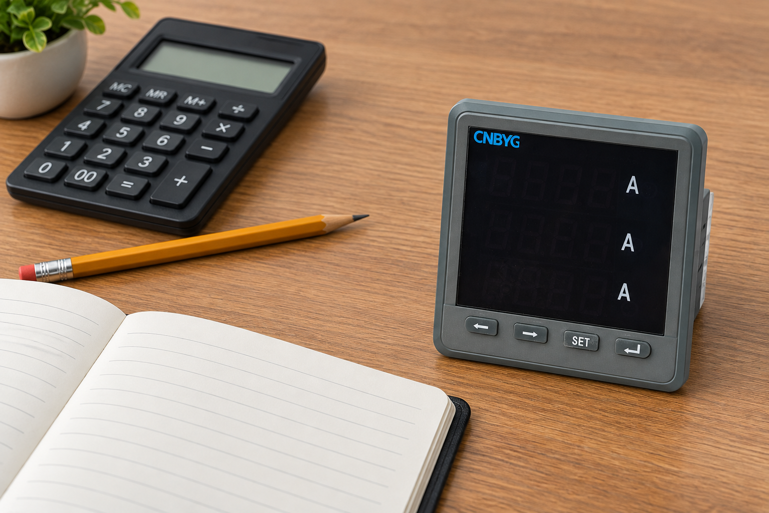
The CNBYG BY194 family page is a starting point for a product enquiry. Confirm the exact ordered variant, supported voltage input, wiring mode, transformer configuration method and communication option. The reference photograph shows an instrument exterior and does not prove that every family variant supports every function discussed here.
Request the settings manual, register map, input limits, scaling explanation and behavior after configuration changes. Supply the transformer ratio, connection drawing, intended primary quantities and reporting units with the enquiry. This allows the supplier to confirm compatibility against a concrete application rather than a generic request for a three-phase meter.
Further learning
The educational lesson below supports the transformer principle behind the calculation. Use the project documents for actual ratings, connections and permitted work.
Frequently asked questions
Is the VT ratio the same as the CT ratio?
No. The VT ratio relates primary and secondary voltage; the CT ratio relates primary and secondary current. A defined secondary power or energy measurement may require both, but a digital register may already include their scaling.
Should a dashboard multiply every meter reading by the transformer ratio?
Only when its documented input still requires that conversion. Confirm the register definition and upstream configuration first. Reapplying a ratio to an already scaled value creates a systematic error.
Can I use line-to-line voltage with a phase-to-neutral secondary value?
Not directly. Establish the winding and measurement basis, convert comparable quantities correctly, and follow the equipment documentation before calculating the ratio.
Does a correct voltage ratio prove the energy reading is accurate?
No. Energy also depends on current scaling, channel pairing, polarity, timing, register interpretation and measurement performance. Verify the complete chain under defined conditions.