Capacitor Bank Maintenance Checklist
Capacitor Bank Maintenance Checklist requires measured site data, not a nameplate-only rule. For preventive maintenance programs for low-voltage capacitor banks, the engineering task is to collect manufacturer instructions, duty cycle, environmental severity, switching count, alarm history and prior inspection records; then make a documented decision about inspection frequency and condition-based actions for capacitors, reactors, contactors, fuses and ventilation. The result must be checked against the equipment manufacturer’s instructions, the approved single-line diagram, local electrical rules, and measurements taken under representative operating conditions. This guide gives a practical workflow for specification, checking, commissioning, and maintenance without treating a generic calculation as a final design.
Start with the operating question
The core keyword capacitor bank maintenance checklist is often used as if it described one fixed answer. It does not. The same nominal equipment can behave differently when the load cycle, source impedance, harmonic spectrum, ambient temperature, or switching method changes. Define the boundary first: which bus is being corrected, which operating states matter, where compliance is assessed, and who owns the final protection settings.
For this application, the most important decision is inspection frequency and condition-based actions for capacitors, reactors, contactors, fuses and ventilation. Write that decision as a testable statement. State the present condition, the desired condition, the measurement point, and the limits that must not be exceeded. This prevents a supplier quotation from becoming the design basis before the site’s real constraints are understood.
Data to collect before selection
Collect manufacturer instructions, duty cycle, environmental severity, switching count, alarm history and prior inspection records. Use synchronized measurements where relationships between voltage, current, kW, kVA, kVAR, power factor, temperature, and harmonic order matter. A single handheld reading may miss production changes, unloaded shifts, automatic stage operation, or intermittent alarms.
| Input | Why it matters | How to verify |
|---|---|---|
| Electrical one-line and equipment ratings | Defines voltage, connection, protection and available fault duty | Compare approved drawings with field labels |
| Representative operating measurements | Shows the real demand and variation the equipment must follow | Trend through low, normal and peak production |
| Power-quality and thermal conditions | Reveals distortion, imbalance, resonance or cooling limits | Record waveforms, spectrum and temperature together |
| Future changes | Prevents immediate undersizing or an unsafe expansion | Review confirmed projects, not speculative load lists |
The table is a decision checklist rather than a substitute for project calculations. If a required input is unknown, mark it as unknown and obtain it. Do not replace missing measurements with optimistic assumptions.
Build the engineering decision in stages
1. Establish the baseline
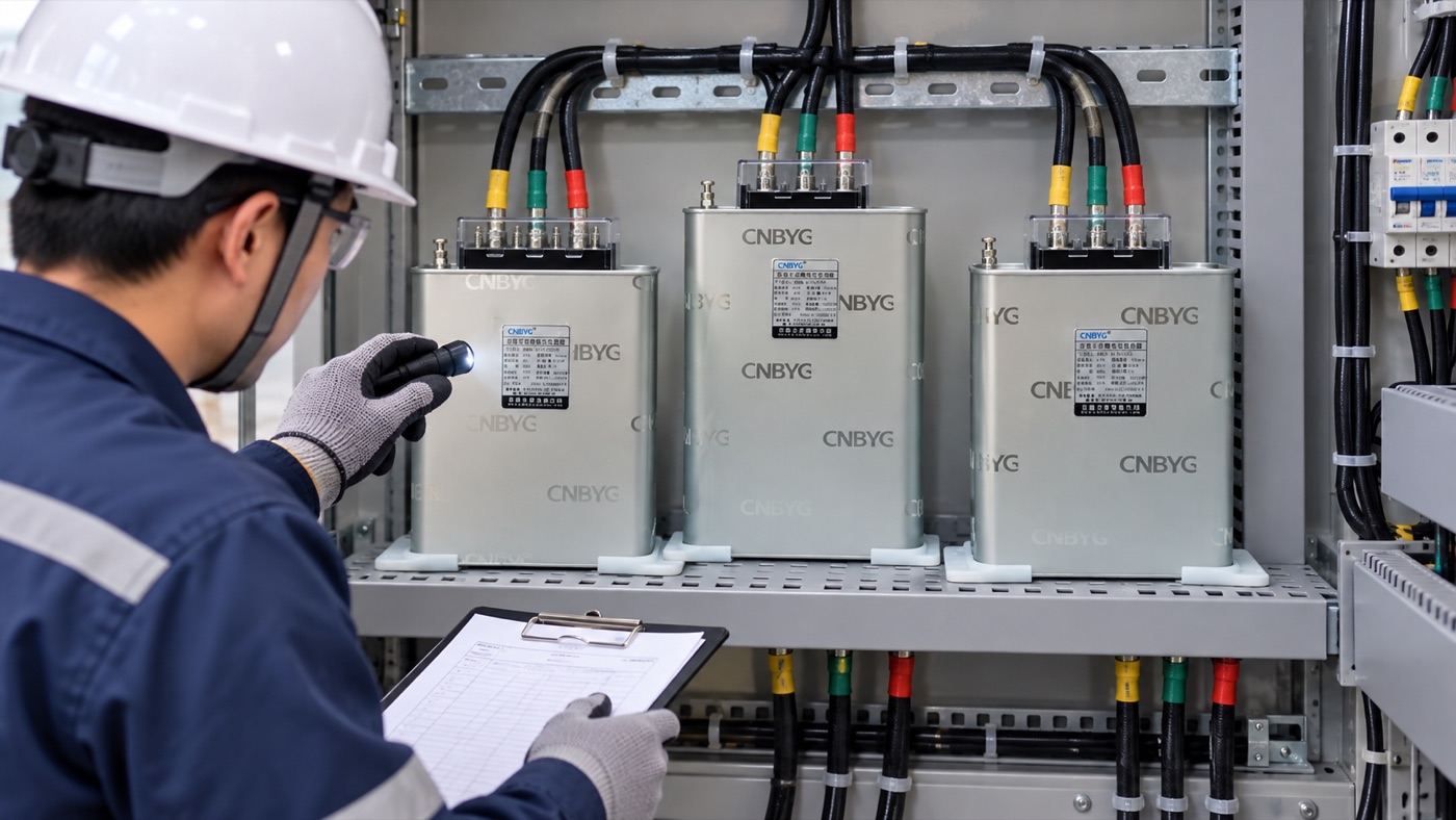
Retain dated measurements so temperature, capacitance and current changes can be reviewed. Save the raw readings, instrument setup, CT ratios, time window and operating state. Baseline records allow later reviewers to reproduce the decision and distinguish a system change from a measurement change.
2. Calculate or compare the required duty
Use the applicable three-phase relationships and the actual connection. For capacitor applications, reactive-power correction is commonly evaluated from the difference between the present and target reactive demand. For active filtering, rating is based on the harmonic and compensation current the filter must inject, including coincidence, diversity and reserve. In both cases, calculation output is a starting duty, not an automatic catalog selection.
3. Apply site constraints
Check voltage variation, altitude, ambient temperature, enclosure heat, switching frequency, short-circuit conditions, harmonics and maintenance access. Confirm every derating rule with the selected manufacturer’s documentation. Do not transfer a factor from another product family or voltage class.
4. Define acceptance tests
Specify what will be measured before and after energization, at which point, for how long, and during which operating state. Include protection, alarms, communications, temperature and abnormal-condition response. Acceptance language should be measurable rather than terms such as “good performance” or “low distortion.”
Protection and safety boundaries
The principal avoidable risk is using a calendar checklist without comparing trends or acting on deterioration. Electrical work must be performed by qualified personnel under the site’s approved procedures. Isolation does not automatically remove stored energy. OSHA requires appropriate de-energizing practices and specifically addresses stored energy in capacitors. Project rules may be more restrictive and always take precedence.
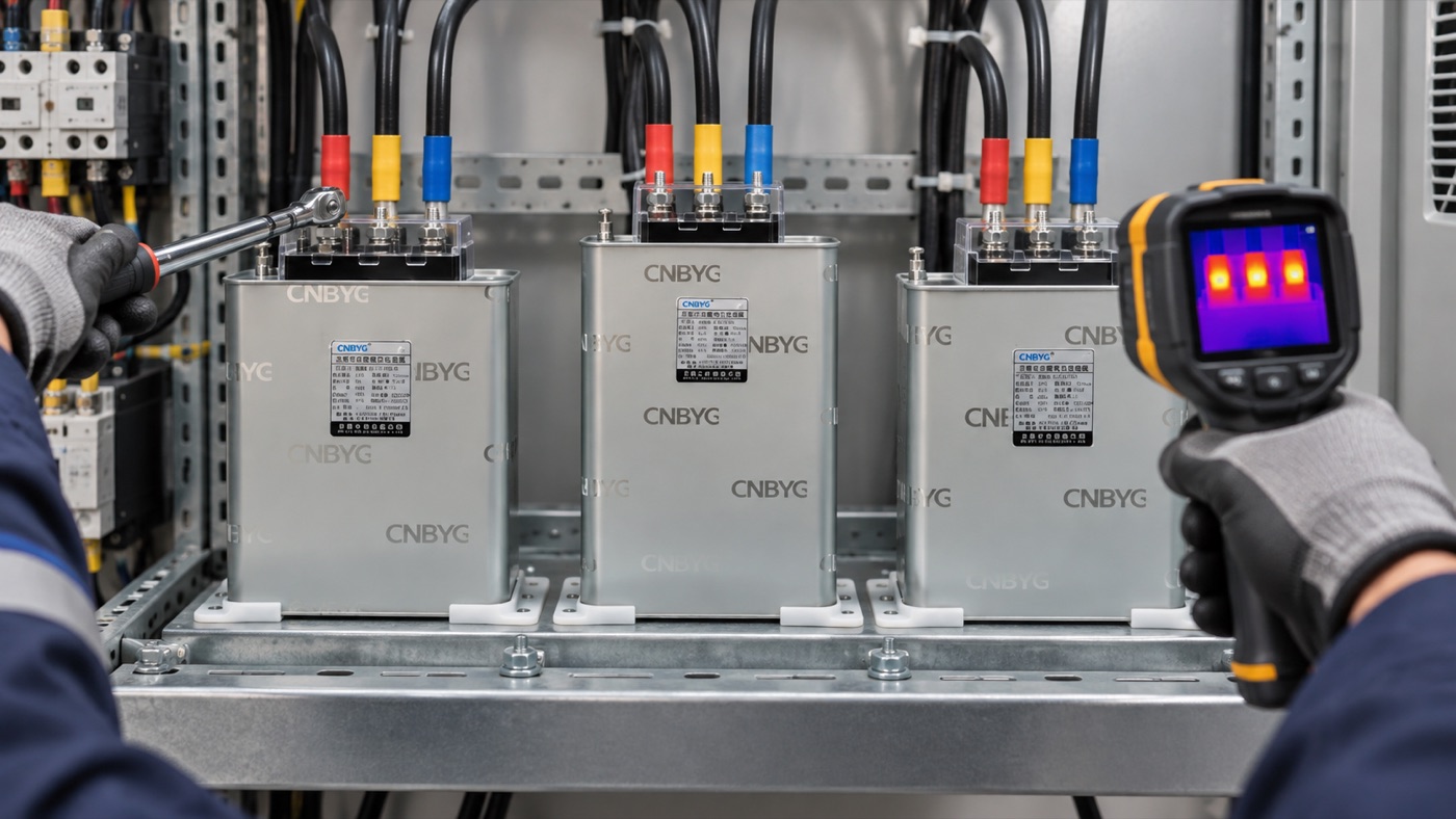
Before contact, identify every source, open the approved disconnecting means, apply lockout and tagging, wait the required discharge interval, verify the tester, prove absence of voltage, recheck the tester, and apply grounding or short-circuiting where the approved procedure requires it. Never infer a safe state from an extinguished display, an open contactor, or elapsed time alone.
Common mistakes and what they reveal
| Mistake | Likely consequence | Better control |
|---|---|---|
| Selecting from connected load alone | Equipment may be oversized, undersized or poorly located | Use measured demand and operating diversity |
| Ignoring the minimum-load condition | Overcompensation, hunting or unstable control can occur | Include low-load and shutdown states in the study |
| Checking only total RMS values | Imbalance and harmonic stress may remain hidden | Review phase values, waveforms and harmonic orders |
| Commissioning without a saved baseline | No defensible before-and-after comparison exists | Freeze the instrument setup and test sequence |
| Changing settings to silence alarms | The underlying wiring, thermal or equipment fault remains | Diagnose the cause and document corrective action |
These failures are not merely paperwork problems. They change current paths, device duty, service life and the credibility of the final acceptance result.
Field verification workflow
A practical verification starts with visual condition, drawing conformity, grounding, connection tightness and ventilation. Next, confirm measurement-channel identity, phase order, CT direction and ratio. Energize in controlled steps while watching current, voltage, alarms and temperature. Stop when readings contradict the expected direction or magnitude.
After stable operation, repeat the baseline measurement using the same instrument setup and similar load condition. Compare the values at the defined measurement point. Record settings and firmware where relevant. Photograph only what site rules permit, and avoid relying on a photograph as proof of electrical performance.
Finally, review the result with operations personnel. Confirm how automatic behavior changes across shifts, how alarms will be handled, what records maintenance will retain, and who may change settings. A technically correct installation can still fail in service when responsibility and change control are unclear.
How this connects to CNBYG equipment
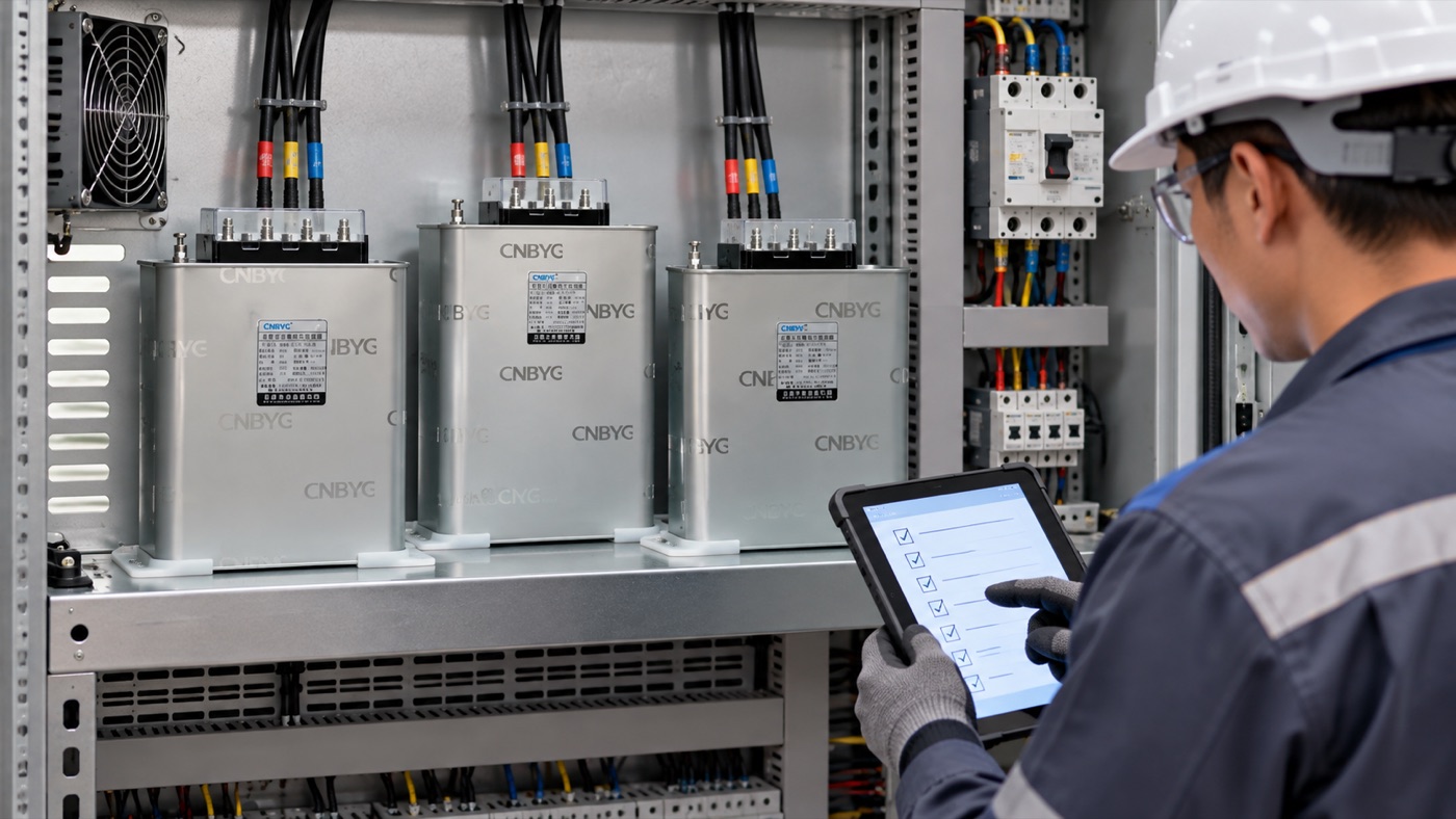
CNBYG supplies equipment used in power-factor correction and harmonic-control projects. Review the relevant product page to identify available product categories, then request project-specific confirmation rather than assuming the page is a final specification. For the broader concept, see the related engineering guide.
Useful supporting reading includes this complementary selection article, this system-design article, and this commissioning-related article. These links address adjacent decisions and are not substitutes for the single search intent covered here.
What to include in an RFQ
- Nominal and operating voltage, frequency, phases and grounding arrangement.
- Measured load data with time range, instrument and CT details.
- Required function, measurement point and acceptance criteria.
- Ambient, altitude, enclosure, ventilation and installation constraints.
- Short-circuit duty, protection philosophy and communication needs.
- Expected operating pattern, switching duty and future confirmed expansion.
- Required drawings, test records, manuals and commissioning support.
A complete RFQ allows suppliers to identify missing data and exceptions early. It also makes quotations comparable because each bidder is responding to the same operating boundary.
Records to retain after handover
A capacitor bank maintenance checklist project should leave an operating record, not only installed equipment. Retain the approved single-line diagram, final settings, protection coordination references, equipment manuals, test certificates, CT information, photographs permitted by the site, baseline measurements and acceptance results. Record the exact operating state used for each test so a later reading can be compared on the same basis.
Add a short change log. Any adjustment to stage sequence, target value, current limit, CT ratio, alarm threshold or compensation priority should show the old value, new value, reason, authorizer and verification result. Uncontrolled setting changes are a common reason that a previously successful installation becomes difficult to diagnose.
Operations staff also need clear response instructions. Define which alarms require immediate isolation, which permit controlled observation, and which call for an engineering review. State the safe inspection boundary and prohibit opening or testing energized equipment except under an approved qualified-person procedure. For preventive maintenance programs for low-voltage capacitor banks, schedule the first follow-up review after representative operation, then use condition trends and manufacturer guidance to set later intervals.
During follow-up, repeat the key baseline measurements, inspect for heat, contamination, looseness, noise, swelling, leakage or fan restriction as applicable, and compare the result with the commissioning record. If the load mix or network configuration has changed, reassess the original selection instead of merely resetting an alarm.
Authoritative references
The following sources support the general calculation, measurement and safety approach. Purchased standards, local regulations, project specifications and manufacturer instructions may impose additional requirements.
- U.S. Department of Energy motor systems guide
- OSHA electrical work practices
- OSHA capacitor work requirements
Educational video
Open the educational video on YouTube. The video is supplementary; the project decision must still use site measurements and approved engineering documents.
Frequently asked questions
Can capacitor bank maintenance checklist be decided from a nameplate alone?
No. Nameplate data defines equipment ratings, but site load variation, harmonics, voltage, temperature, protection and the intended measurement point must also be checked.
What measurement should be saved before installation?
Save time-stamped voltage, current, kW, kVA, kVAR, power factor and relevant harmonic or thermal data with the operating state and instrument setup.
Who should perform commissioning?
Qualified personnel following the approved design, manufacturer instructions, site safety procedures and applicable local rules should perform and document commissioning.
When should the design be reviewed again?
Review it after major load changes, repeated alarms, protection operation, abnormal temperature, significant power-quality changes or planned capacity expansion.