Power Data Logger: Measurement, Selection and Use Guide
A power data logger records time-stamped electrical measurements so engineers can see how voltage, current, power, energy, power factor and related quantities change over hours, days or weeks. It is most useful for load profiling, energy studies, capacity planning and intermittent fault investigation. Reliable results depend on the correct measurement point, sensor ranges, wiring configuration, interval, clock, storage, scaling and operating log—not merely on leaving an instrument connected.
What the equipment or concept is intended to achieve
The engineering purpose is to turn changing electrical behavior into a time series that can be compared with production, weather, control actions, alarms and utility billing intervals. Typical applications include factories, buildings, renewable systems, temporary projects, generator studies and equipment commissioning. A reliable project begins by defining the decision the equipment must support, the electrical boundary, the operating states and the evidence required for acceptance. Product names can be similar while their ratings, measurement methods, protection and lifecycle responsibilities are materially different.
Search results often emphasize product lists or supplier claims. A usable specification instead connects the operating problem to measurement question, channels, sensor range, sampling versus logging interval, event capture, storage, time synchronization, data export and interpretation. It also states what is outside scope. That prevents a supplier from satisfying the words of a request while missing the actual duty.
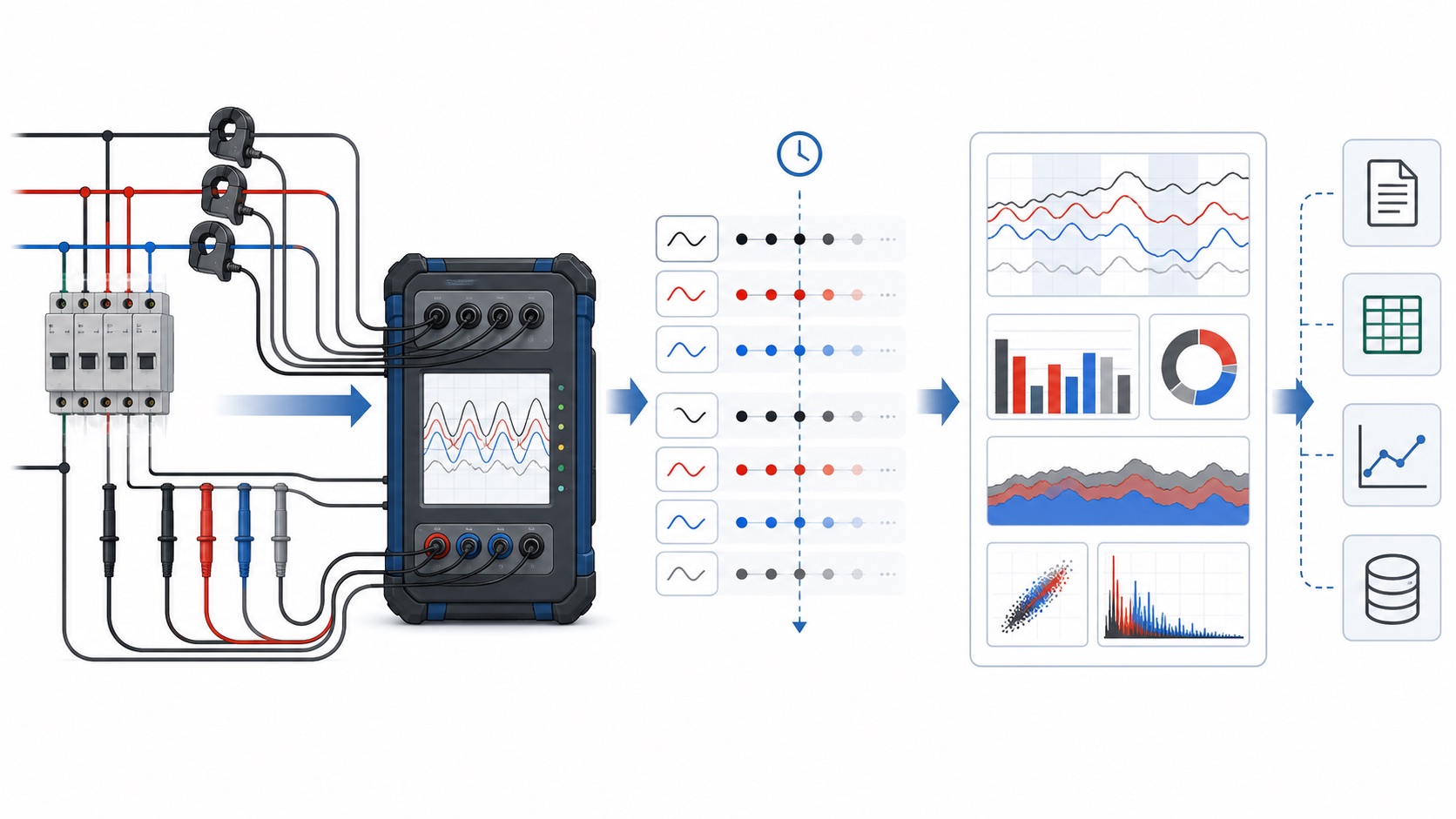
Start with a one-line diagram and operating profile
Mark the proposed connection point on an up-to-date one-line diagram. Record nominal voltage, frequency, conductor arrangement, grounding method, available fault information, upstream protection and the loads that can operate at the same time. Identify normal production, start-up, shutdown, standby, generator operation, maintenance bypass and credible abnormal states. A design checked only at average load can fail during the short condition that matters most.
Where measurements are involved, define whether the objective is indication, control, energy allocation, troubleshooting or compliance. Each purpose changes the required accuracy, time resolution and record retention. Where power equipment is involved, define continuous rating, temporary duty, redundancy, cooling, access, isolation and recovery after a fault. Keep assumptions in the project file and ask suppliers to list deviations explicitly.
Selection matrix
| Decision area | Evidence required | Common mistake |
|---|---|---|
| Study question | State the capacity, energy or fault decision the data must support | Logging every available channel without a purpose |
| Sensors | Match range, conductor size, bandwidth and accuracy | Using an oversized clamp for a small load |
| Interval | Choose a period that preserves relevant variation | Using long averages that hide short peaks |
| Time | Synchronize logger, plant and utility clocks | Comparing trends with shifted timestamps |
| Export | Confirm raw data, units, scaling and file format | Keeping only screenshots of graphs |
The matrix is deliberately qualitative because final numerical ratings must come from the project study, selected equipment documentation and applicable standards. Copying a value from a different installation can hide differences in voltage, fault duty, temperature, cable length, load behavior or tariff rules.
Electrical measurement and power-quality context
Voltage and current readings should be associated with the correct phase, direction and timestamp. For three-phase work, verify the wiring configuration and sensor orientation before trusting calculated power. Real power describes the rate of useful energy transfer, while reactive power and apparent power affect current and capacity. Our guide to active and reactive power explains these relationships, and the BY194 multifunction power instrument shows how a permanent panel meter can support continuous plant monitoring.
Nonlinear loads can distort waveforms and make simple assumptions unreliable. Harmonic current, voltage distortion, unbalance and rapidly changing demand may influence equipment selection or explain unexpected readings. Review the measurement approach described in our VFD harmonics guide. When mitigation is being considered, understand the active harmonic filter working principle before sizing equipment from a single snapshot.
Safety and installation boundaries
Electrical installation, temporary measurement and energized inspection can expose personnel to shock, arc-flash and stored-energy hazards. Work must be planned and performed by qualified personnel using the site’s approved isolation, verification, PPE and access procedures. The OSHA electrical safety resources provide general workplace guidance, but they do not replace local rules, the equipment instructions or a project-specific risk assessment.
Use components and instruments explicitly rated for the circuit, environment and measurement category. Confirm conductor temperature, terminal capacity, enclosure integrity, protective-device interruption duty and safe working clearances. For temporary leads, prevent movement, abrasion and accidental disconnection. For stored-energy systems, verify discharge and isolation rather than assuming loss of AC input makes the equipment safe.
Commissioning and data-quality checks
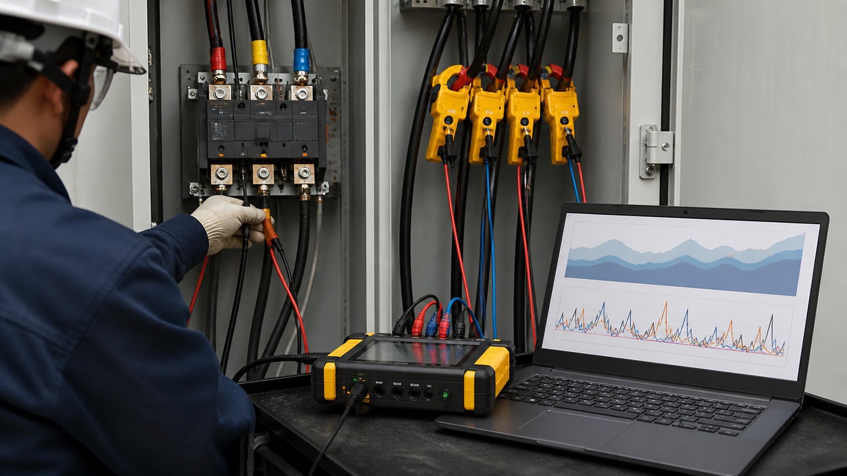
Commissioning should prove the complete information path and operating sequence. Compare the installed configuration with approved drawings, confirm ratings and settings, inspect workmanship, verify polarity or phase association, and test alarms or communications at their final destination. Record baseline readings under a known operating condition. If values are unexpected, investigate before applying correction factors or accepting the system.
For logged data, retain raw files, units, scaling, timestamps, instrument configuration and site notes. Screen for gaps, clipped ranges, reversed signs and impossible values. A polished graph cannot repair incorrect CT orientation or a shifted clock. For power equipment, record protection tests, functional sequences, thermal conditions and any deviations from the factory configuration. Acceptance evidence should allow another engineer to understand what was tested and under which conditions.
Practical project checklist
- Draw the one-line and select the measurement boundary.
- Check three-wire or four-wire configuration.
- Confirm CT orientation and scaling.
- Record phase labels and connection photos.
- Set a logging interval tied to the decision.
- Keep a site event and production log.
- Review storage before the study ends.
- Export raw values with timestamps and units.
- Screen for missing samples and impossible values.
- Archive configuration, firmware and analysis assumptions.
These checks create a traceable path from the initial question to the installed or rented solution. They also reduce commercial disputes: the supplier can quote a defined duty, the installer can work from an approved drawing, and the owner can compare acceptance results with the original requirement.
Common failure modes and how to verify the result
Many unsuccessful projects begin with an ambiguous boundary. The source is measured at one location, the load is described at another, and the quoted equipment is rated under conditions that do not exist at the site. Other failures come from reversed sensors, incorrect ratios, undocumented default settings, insufficient accessories, incompatible communications, or data captured during an unrepresentative operating period. Treat every unexpected result as a prompt to check the measurement chain and configuration before concluding that the electrical system changed.
Verification should answer the original decision in measurable terms. Compare final ratings and settings with the approved requirement; repeat representative operating states; confirm alarms and exported data; and record limitations. When before-and-after performance is important, use comparable production, weather and source conditions and retain both raw datasets. If a supplier calculation depends on an assumed load, temperature, tariff, fault level or duty cycle, replace that assumption with project evidence or clearly preserve it as a boundary on the conclusion.
Maintenance and lifecycle planning
Set inspection and test intervals from the equipment manufacturer, environment, duty and site criticality. Review alarms and trends rather than waiting for a visible failure. Changes in loading, temperature, connection resistance, battery condition, insulation, cooling or communications can progressively remove design margin. After a plant expansion or configuration change, repeat the capacity and protection review instead of assuming the original study remains valid.
Maintain drawings, settings, firmware, calibration evidence, spare-parts records and test history under change control. Cyber-connected meters and controllers also need account ownership, network segmentation, backup and recovery arrangements. The NIST Cybersecurity Framework provides a general risk-management structure that owners can translate into controls appropriate to the system.
How to write the purchase or rental specification
State the core keyword topic in plain engineering terms, then attach the one-line, operating profile, environment, required functions, interfaces, documentation, tests and delivery scope. Distinguish mandatory requirements from preferences. Require a compliance schedule with model numbers and document references. If an assumption affects rating, safety, accuracy, runtime or compatibility, it should not remain inside a salesperson’s email.
Ask who is responsible for design review, installation, commissioning, training, software, calibration, batteries or accessories, spares, warranty work and return logistics. Define the final deliverables: drawings, manuals, certificates, test reports, configuration backups, raw data and an exceptions list. For custom panel integration or sourcing discussions, CNBYG’s OEM and ODM service can review a documented requirement without inventing project ratings.
Video: electric power fundamentals
This Khan Academy lesson reviews the relationship among voltage, current and power. It is background learning and does not replace equipment manuals, tariff documents, project calculations or safe-work procedures.
Frequently asked questions
What is the difference between sampling rate and logging interval?
Sampling describes how the instrument observes the signal; the logging interval describes how often summarized or selected values are stored.
How long should a logger remain installed?
Long enough to cover representative operating cycles, including the event or demand condition the study is intended to explain.
Can a power logger capture transients?
Only if its hardware and configuration include the required event or waveform capability; many energy loggers store slower trends.
Why is CT orientation important?
Reversed or mismatched sensors can produce incorrect sign, phase and power calculations.
What data should be archived?
Keep raw files, configuration, connection records, timestamps, operating notes, software version and the final analysis.