Energy Meter Accuracy Verification: Reference Tests and Error Budgets
Energy meter accuracy testing compares a meter’s registered energy with a suitable reference under defined conditions. A useful result states the connection arrangement, test point, elapsed observation, reference uncertainty and acceptance rule. Comparing a dashboard with an electricity bill can reveal a discrepancy, but it does not isolate the meter’s intrinsic error. For an industrial installation, verify the complete measurement chain as well as the instrument. This guide explains how to plan a defensible comparison, calculate percentage error and distinguish a practical screening check from a documented calibration or regulated billing investigation.
Define which question the test must answer
There are several legitimate reasons to check a meter. A commissioning team may need to confirm wiring and scaling. An energy manager may investigate disagreement between two reports. A purchasing department may require evidence that a supplied instrument meets its declared performance. A billing dispute may require a formally recognized process. These tasks need different evidence and authority.
Write the question before choosing the test equipment. A short field comparison may identify a reversed CT or an incorrect multiplier, while a laboratory test can examine performance across controlled operating points. Neither automatically replaces the other. The test report should state what was actually examined, rather than using a broad label such as certified accurate without qualification.
For regulated electricity billing in Great Britain, the UK government’s independent meter accuracy guidance describes a specific route for unresolved concerns. It is a jurisdiction-specific process, not a universal acceptance procedure for every industrial submeter. Contact the relevant supplier or authority when legal settlement is involved.
Separate meter error from installation error
The installed result depends on voltage sensing, current sensing, phase association, connection mode, programmed transformer ratios and data interpretation. A highly accurate instrument can report the wrong primary energy when a CT ratio is programmed incorrectly. Correcting that configuration does not mean the instrument itself was recalibrated.
Start with the approved single-line and wiring documents. Check the instrument model, input type, serial number and configuration against the installation. Confirm that voltage and current channels correspond to the same phase and that current direction is correct. Do not infer correct power measurement solely from plausible voltage and current magnitudes.
The multifunction meter wiring and commissioning checklist addresses installation review. For transformer selection and the consequences of its characteristics, use the CT selection guide. Keep the present test focused on an explicitly defined measurement boundary and documented test conditions.
Choose a reference suitable for the intended decision
A reference instrument should have documented calibration status and uncertainty appropriate to the acceptance decision. A second unverified meter is useful for finding disagreement but cannot establish which instrument is correct. The reference’s current sensors, voltage leads, connection method and operating range are part of the reference measurement system.
Review the calibration certificate for its scope, date, measurement points and reported uncertainty. Confirm that the actual accessories and ranges used in the comparison are covered. A certificate for a basic voltage function does not necessarily establish performance for three-phase energy under a distorted waveform. Similarly, a laboratory’s accreditation is meaningful only in relation to its applicable scope.
NIST’s metrological traceability guidance explains why traceability belongs to a measurement result and depends on documented calibration links and uncertainty. Possessing a calibrated instrument alone does not establish the quality of every result obtained with it. Apply that distinction when reviewing the actual reference setup and comparison report.
Calculate percentage error with a clear sign convention
For a comparison of accumulated energy over the same test interval, define percentage error as the device-under-test energy minus reference energy, divided by reference energy, multiplied by one hundred. Under this convention, a positive result means the tested meter registered more energy than the reference. Record the convention explicitly because reports may use different terminology.
For example, if the reference records 10.000 kWh and the tested meter records 10.060 kWh, the indicated error is positive 0.60%. These are illustrative arithmetic inputs, not measured CNBYG performance. A result of that size is neither automatically acceptable nor unacceptable: the applicable specification, test conditions, uncertainty and decision rule determine the conclusion.
Use period changes in cumulative registers rather than comparing absolute lifetime totals. Confirm whether readings are already scaled to primary energy. If the reference measures primary quantities while the tested meter exposes secondary quantities, apply the documented transformation once and show it in the calculation. Keep the original readings in the report so the arithmetic can be checked independently.
| Test record | Why it matters | Evidence to request |
|---|---|---|
| Instrument identity | Ties the result to a supplied device | Model, serial number, firmware and input arrangement |
| Reference system | Establishes the basis of comparison | Instrument and sensor identities, certificates and applicable uncertainty |
| Operating point | Defines where the result applies | Voltage, current, frequency, power factor and relevant waveform conditions |
| Comparison interval | Prevents mismatched accumulation | Synchronized start/end evidence and register resolution |
| Scaling | Separates primary and secondary quantities | CT/VT ratios, programmed multipliers and register units |
| Decision rule | Explains how the result becomes acceptance | Applicable requirement and treatment of measurement uncertainty |
| Restoration | Confirms safe return to service | Configuration record and authorized completion checks |
The checklist is qualitative. It does not prescribe a generic current range, test voltage or allowable percentage error for all meter classes.
Allow enough accumulated energy for a useful comparison
Register resolution matters when the test is short. If a display changes only in relatively coarse energy increments, a small test quantity can make rounding dominate the calculated percentage difference. Extending the observation under suitable stable conditions can improve the usefulness of the comparison, but it does not remove reference uncertainty or installation errors.
As an arithmetic illustration, a 0.01 kWh display increment is one percent of a 1 kWh test quantity, but only one tenth of one percent of a 10 kWh test quantity. That does not establish a complete uncertainty budget, since start and end rounding, timing and other influences still matter. It explains why a very brief comparison may be inconclusive even when the instruments are functioning normally.
Where a supported pulse output is used, confirm the pulse constant, direction, scaling and counting interval before calculating energy. The energy meter pulse output guide covers those conversion details. A correct pulse calculation is only one part of an accuracy test and does not automatically establish the performance of the complete measurement chain.
Match the conditions to the claimed performance
Meter accuracy declarations apply under specified conditions. A comparison at one convenient load cannot establish performance across the whole input range, power factor range and environmental envelope. Determine which points are required by the applicable standard, contract or manufacturer specification, and have a competent laboratory design the formal test where necessary.
Real industrial loads may vary during a field comparison. Switching drives, changing production and reactive compensation can affect current, power factor and waveform shape. Record enough operating context to explain whether the two systems observed the same electrical state. Comparing nonsimultaneous averages during a rapidly changing process is a poor way to isolate small measurement errors.
Do not invent generic pass limits for harmonics, temperature, starting current or no-load behavior. If a particular performance claim matters to procurement, request the relevant declared specification and corresponding test evidence. A simple display photograph cannot substitute for a report showing how that requirement was tested.
Treat uncertainty and acceptance as separate steps
The measured difference is an estimate. Reference uncertainty, sensor behavior, repeatability, resolution, timing and connection effects limit how confidently it can be interpreted. A result close to a contractual limit deserves particular attention to the agreed decision rule. Reporting extra decimal places does not make the underlying evidence stronger.
For an internal screening check, it may be enough to classify the outcome as consistent, clearly discrepant or inconclusive under a documented procedure. For formal acceptance, specify the applicable uncertainty treatment before testing. Otherwise, different reviewers can reach different conclusions from the same numbers because they silently apply different rules.
Repeat the comparison when an unexplained discrepancy remains, but change one suspected cause at a time and preserve the original result. Correcting a multiplier, replacing a sensor and changing software decoding simultaneously makes it difficult to establish which action resolved the problem. An auditable sequence is more useful than a final screenshot showing agreement.
Keep electrical safety inside the approved test plan
Field testing can expose personnel to live electrical hazards and CT secondary risks. Only qualified personnel should perform work under the site’s authorized procedures. A portable comparison instrument does not make an installation safe to access. Use the equipment manufacturer’s connection instructions and the site’s isolation and restoration requirements.
Do not open an energized conventional CT secondary or improvise a test circuit from an online example. Where a test requires equipment removal, interruption or specialized injection, arrange the appropriate controlled procedure. This article provides planning and interpretation guidance, not an instruction to perform live calibration or bypass protective arrangements.
Ask suppliers for a complete accuracy evidence package
Specify whether you need internal energy monitoring, process allocation or legally regulated revenue metering. Request the exact model’s declared class and applicable standard, input range, transformer arrangement, relevant conditions and test documentation. Include the communication data format if the accepted value will be read into software rather than taken from the front display.
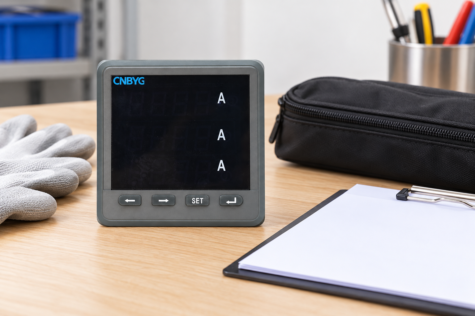
The CNBYG BY194 series page contains several instrument variants. Its general description does not establish one energy accuracy class, calibration uncertainty or billing approval for every model. The pictured ammeter exterior likewise does not prove an energy-register function. Obtain the supplied-model documentation and required certificates before accepting a purchase specification.
Retain the test report, raw readings, configuration, sensor identities and restoration record together. Assign a review trigger after instrument replacement, transformer changes, unexplained register discontinuities or material disagreement with a trusted reference. Set any routine verification interval from risk, service history and applicable requirements, rather than inventing one universal annual rule.
Educational video: how an energy meter measures
The NPTEL IIT Kharagpur lecture below explains single-phase energy-meter principles. It supports understanding what an energy measurement represents. It is not a calibration procedure for a modern three-phase instrument, a substitute for the supplied manual or evidence of a CNBYG model’s accuracy.

Frequently asked questions
Can a comparison with the utility bill prove meter accuracy?
No. Billing periods, measurement boundaries, tariffs, losses and scaling can differ. The comparison can reveal a discrepancy, but a defined reference test is needed to isolate the instrument’s measurement error.
Does an accurate voltage display prove accurate energy measurement?
No. Energy measurement also depends on current sensing, phase association, timing, power factor and configuration. Plausible voltage and current readings can coexist with incorrect active power or energy.
What percentage error should every energy meter meet?
There is no single limit appropriate to every meter and application. Use the exact declared specification, applicable standard, test conditions and agreed uncertainty-based decision rule for the required acceptance.
Can a second ordinary meter serve as the calibration reference?
It can help identify disagreement, but an unverified second instrument does not establish which result is correct. Formal verification requires a reference system with suitable documented calibration and uncertainty.