Power Meter RS485 Termination: Cable Ends, Biasing and Fault Isolation
Power meter RS485 termination belongs at the physical ends of the communication trunk, with the termination network selected to match the cable and equipment design. It does not belong automatically at every meter. Before changing resistors, identify the actual trunk ends, existing built-in termination and any biasing network. Then investigate communication failures with controlled read-only tests and an approved electrical work procedure. A missing reply alone does not prove a termination fault: addressing, serial format, cable continuity, interference and gateway timing can produce similar symptoms.
This guide addresses the physical communication line. Use the power meter Modbus setup guide for serial settings and register configuration. No terminal number, resistor value or communication option in this article should be treated as an undocumented BY194 product specification.
Confirm the supplied interface and network drawing
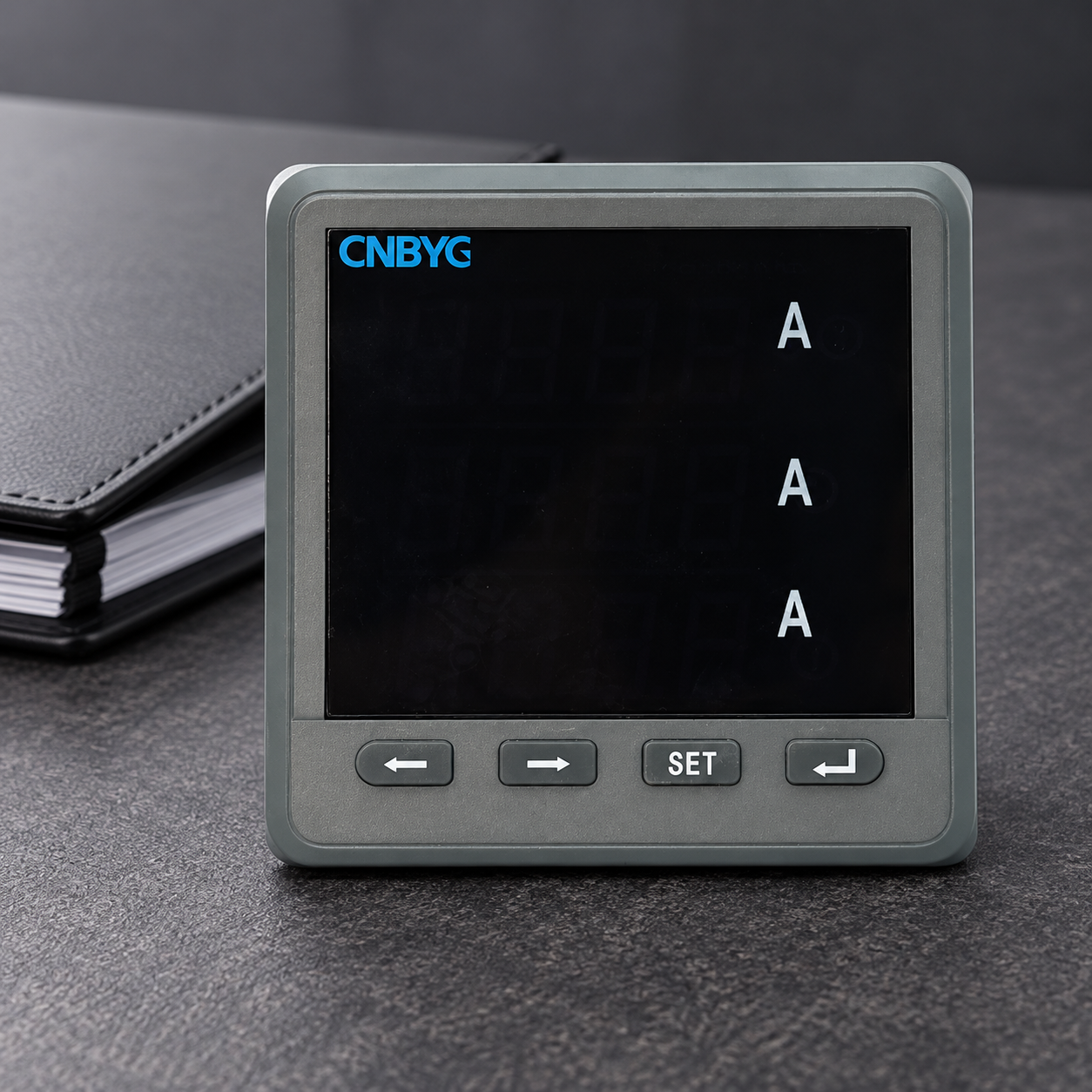
Start with the exact meter order code and installation instructions. The CNBYG BY194 product family is relevant to panel metering, but the exterior photograph does not identify a fitted communication option, transceiver, internal termination or supported topology. Obtain the applicable model documentation before adding or removing line components.
Collect the cable route, device positions, converter or gateway model, approved grounding arrangement and maintenance history. A logical drawing that lists addresses may omit the physical cable route. Walk down that route through an authorized inspection, because the electrical end of a trunk can be in the middle of an address list or on another floor.
Identify repeaters and isolated segments separately. A repeated network can contain multiple independently driven cable segments, each with its own design requirements. Counting two resistors across an entire site is not a valid acceptance test when the installation includes several physical segments. Mark the boundaries before evaluating termination quantity.
Understand the purpose of termination
An RS485 cable carries differential signals. A change in impedance, including an improperly treated cable end, can reflect part of a travelling signal. Reflections can distort the receiver’s signal around transitions. Whether that distortion causes errors depends on cable properties, propagation time, driver edge behavior, loading and the receiving arrangement.
The Modbus serial-line specification describes termination at the two ends of a passive balanced pair and excludes termination on a derivation cable. That is a physical-layer rule for the relevant bus arrangement, not a reason to put a resistor beside every device on a multidrop line.
The Texas Instruments RS485 design guide explains impedance matching, short stubs and receiver behavior. TI supplies interface components rather than the CNBYG meter discussed here; this reference supports general interface engineering and does not establish the instrument’s fitted electronics or approve a particular installation.
Select a documented termination network
A common RS485 example uses a cable with nominal 120-ohm characteristic impedance and matching resistors at the two ends. That example is not a universal replacement part. Cable specifications, equipment instructions, biasing arrangements and the approved design determine the actual network and its component ratings.
The Modbus serial guide also describes other termination arrangements, including a resistor-capacitor option in conjunction with line polarization. Consequently, a technician should not declare every installation incorrect because it differs from a simple pair of 120-ohm resistors. Determine which design applies and compare the actual circuit with that design.
Built-in termination may be controlled by a switch or configuration arrangement. Confirm its function in the relevant manual rather than inferring it from an unlabeled switch position. If a gateway already terminates a cable end, adding an external resistor at the same location can increase loading unnecessarily. Record both internal and external components.
Distinguish termination from biasing and shielding
Termination reduces reflections by addressing line impedance. Biasing or polarization establishes a suitable idle-line condition when the applicable receiver and network require it. Shielding addresses interference control as part of the installation design. These functions are related to communication reliability, but they solve different problems and are not interchangeable.
Some modern receivers provide internal failsafe behavior. That does not justify guessing the needs of every connected device. Review the requirements for all devices sharing the segment and identify any existing external polarization. Duplicated bias networks can change loading and idle voltages, while a missing required network can leave the receiver vulnerable during idle periods.
Follow the equipment and site instructions for reference conductors, isolation and shielding. Never use a shield as an assumed substitute for a specified signal reference. A communication article cannot determine the correct bonding scheme for an unknown plant, especially where equipment spans different electrical reference environments.
Use a fault-isolation table before making changes
| Observation | Evidence to collect | Next controlled check | What it does not prove |
|---|---|---|---|
| Every device is silent | Client state, serial settings, supply and approved wiring | Establish one documented read on an authorized test arrangement | Termination is missing |
| One meter is silent | Address allocation and local device condition | Compare identity and configuration with its manual | The whole trunk needs another resistor |
| Errors increase after adding a device | Updated cable route, loading and configuration | Inspect the new branch and duplicate settings | The new meter is defective |
| Errors follow a cable extension | Previous and current endpoint locations | Verify the new trunk end and installed components | Higher baud rate is the only cause |
| Replies are valid but values are implausible | Raw payload and register map | Check decoding, units and scale | Reflections caused the numeric error |
| Idle periods precede false frames | Receiver requirements and existing bias network | Review the documented idle-line design | Extra termination will fix biasing |
This table organizes diagnosis; it does not provide product limits or authorize live electrical access. Compare each observation with the Modbus and interface references above, the model instructions and the site’s approved test procedure.
Plan safe inspection and resistance measurements
Only qualified personnel should work on installed metering equipment. Communication terminals can be located near energized measurement inputs or auxiliary supplies. Follow the site’s isolation, verification and access procedure. Do not assume a low-voltage communication function makes the entire enclosure safe to open or probe.
A resistance measurement across a de-energized, appropriately isolated pair can sometimes help identify installed resistors. Two ideal 120-ohm resistors in parallel would calculate to 60 ohms. That arithmetic is a circuit example, not an acceptance range for an installed network: bias circuits, connected electronics, cable resistance and other paths can change what an instrument measures.
Do not measure resistance on a live communication pair. Establish the circuit condition and permissible test method from the approved procedure. If readings do not match a simple calculation, investigate the actual connected circuit instead of removing components until a preferred number appears. Retain the before-and-after drawing with any authorized change.
Keep topology and stubs visible in the investigation
A trunk with short device connections differs from an uncontrolled star containing long branches. Adding endpoint resistors cannot necessarily repair reflections created by unsuitable branches. Determine whether the equipment supports the installed layout and whether repeaters or a redesigned route are required under the engineering specification.
Keep derivation lengths and component positions in the evidence pack. A cabinet drawing can make a branch look short even when the actual cable takes a long route through a building. Electrical behavior depends on the installed route and signal edges, so physical measurements and model guidance matter more than the drawing’s visual proportions.
After a cable extension, the previous end device may become an intermediate device. Review its termination and the new endpoint together. A common maintenance error is adding a new end resistor while retaining one at the former end, creating additional loading on a line that previously worked.
Verify the result through communication evidence
Use a repeatable read-only test with a stable request list. Record successful replies, timeouts, reported frame or CRC errors, elapsed transaction times and affected device addresses. Compare similar operating periods before and after an authorized correction. One successful reply does not establish stable operation across the segment.
Keep decoding checks separate. A CRC-valid frame with a consistently wrong engineering value calls for a map and conversion review. Compare the meter measurement chain and the voltage scaling workflow where appropriate. Physical-line improvements cannot establish correct CT scaling or measurement placement.
If the problem occurs only with a large request load, review transaction scheduling and device response behavior as well as wiring. A device can time out because requests overlap or the controller retries too aggressively. Avoid changing cable components to compensate for a scheduling problem without evidence that the physical layer is deficient.

Preserve a useful maintenance record
Record the final segment drawing, cable type, endpoint locations, termination network, bias ownership and switch positions established from manuals. Include photographs taken under an authorized procedure and the test conditions used to verify communication. Identify any remaining uncertainty rather than replacing it with a guessed default.
For procurement, ask whether termination and biasing are built in, optional or externally supplied, and request the interface installation instructions. Also confirm isolation requirements and the supported network architecture. These questions reduce the chance that a panel builder and integrator each assume the other supplied the required components.
Assign responsibility for reviewing the network after device replacement or cable extension. The replacement can have different internal behavior even when the front panel looks similar. Recheck the approved segment design and repeat the communication test before returning the network to routine monitoring.
Further learning: reflections at a line boundary
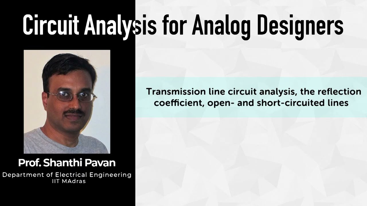
The NPTEL lesson below explains transmission-line reflection and boundary conditions. It supports the reason termination matters; it is not a meter wiring demonstration or an instruction to use a particular resistor value.
Frequently asked questions
Should every meter have a terminating resistor?
No. Determine the physical segment and its endpoints. For the applicable passive two-wire bus, termination belongs at the ends according to the approved design, rather than at every intermediate device.
Is 120 ohms always the correct termination value?
No. It is a common example for matching a specified cable impedance. Follow the cable, equipment and engineering requirements, including any documented resistor-capacitor arrangement.
Does a 60-ohm resistance reading prove the line is correct?
No. That value follows from two ideal 120-ohm resistors in parallel. Actual connected circuits can change the reading, and resistance alone cannot verify topology, shielding or signal quality.
Can termination fix valid replies with incorrectly scaled values?
It does not establish correct numeric interpretation. Investigate addresses, representation, units, CT and voltage scaling separately when frames are valid but values are wrong.